
- LG Software Innovations Coffeemaker User Manual
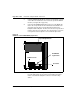
Table Of Contents
- Title Page
- Revision history
- Contents
- About this guide
- Description
- System requirements
- List of ITG ISDN components
- Ordering rules and guidelines
- ITG ISL Trunk card description
- ITG ISL Trunk card physical description
- ISDN Signaling Link
- Dialing plans
- Quality of Service
- Fallback to alternate facilities
- Type of Service
- Fax support
- Remote Access
- Per-call statistics support using RADIUS Client
- SNMP MIB
- Codec profiles
- Security passwords
- ITG Engineering Guidelines
- Introduction
- Network engineering guidelines overview
- ITG traffic engineering
- Configuration of Meridian 1 routes and network translation
- Assess WAN link resources
- QoS Evaluation Process Overview
- Set QoS
- Measure intranet QoS
- Implement QoS in IP networks
- ITG Trunk DSP profile settings
- Post-installation network measurements
- Estimate QoS level
- ITG MAT PC management configuration
- Install and configure ITG ISL Trunk node
- Before you begin
- Installation Procedure Summary
- Create the ITG Trunk Installation Summary Sheet
- Install and cable ITG trunk cards
- Install NTCW84JA Large System I/O Panel 50-Pin filter adapter
- Install NTMF94EA and NTCW84KA cables
- D-channel cabling for the NT0961AA 24-Port ITG Trunk card
- Set NT6D80 MSDL switches
- Install filter and NTND26 cable (for MSDL and DCHIP cards in same Large System equipment row)
- Install filter and NTND26 cable (for MSDL and DCHIP cards in different Large System equipment rows)
- Configure ITG Trunk data on the Meridian 1
- Configure dialing plans within the corporate network
- Configure ITG Trunk data on MAT
- Transmit ITG trunk card configuration data from MAT to the ITG trunk cards
- Set date and time for the ITG ISL Trunk node
- Change the default ITG shell password to maintain access security
- Change default ESN5 prefix for non-ESN5 IP telephony gateways
- Check card software
- Configure MAT Alarm Management to receive SNMP traps from ITG ISL Trunk cards
- Make test calls to the remote ITG nodes
- Upgrade an ITG Trunk 1.0 node to support ISDN signaling trunks
- Upgrade procedure summary
- Before you begin
- Install the DCHIP hardware upgrade kit
- Upgrade the 8-port ITG basic trunk software to ITG ISL trunk software
- Remove ITG 1.0 configuration data from Meridian 1
- Configure the Meridian 1 ITG ISL Trunk data: upgrade considerations
- Verify ROM-BIOS version
- Upgrade Troubleshooting
- OA&M using MAT applications
- OA&M using the ITG shell CLI and overlays
- Maintenance
- Appendix A: Calbe description and NT8D81BA cable replacement
- NTMF94EA E - LAN, T - LAN and Serial Port cable
- NTCW84KA E-LAN, T-LAN, DCH & Serial cable
- NTAG81CA Faceplate Maintenance cable
- NTAG81BA Maintenance Extender cable
- NTCW84EA DCH PC Card Pigtail cable
- NTMF04BA MSDL extension cable
- NTCW84LA and NTCW84MA upgrade cables
- Prevent ground loops on connection to external customer LAN equipment
- Replace cable NT8D81BA with NT8D81AA
- Tools list
- NT8D81BA cable removal procedures
- Appendix B: Environmental and electrical regulatory data
- Appendix C: Subnet mask conversion from CIDR to dotted decimal format
- Appendix D: Configure a Netgear RM356 modem router for remote access
- Index
- Back

Install and configure ITG ISL Trunk node Page 159 of
378
ITG Trunk 2.0 ISDN Signaling Link (ISL) Description, Installation and Operation
Note 1: The ITG Trunk card requires 24 pair tip and ring I/O cabling.
NT8D37AA IPE modules have 24 pair tip and ring I/O cabling for card
slots 0, 4, 8, and 12 only. You can insert the left slot of the ITG Trunk
card in NT8D37AA slots 0, 4, 8 or 12 only. NT8D37BA or later IPE
modules have no such restriction.
Note 2: When multiple ITG cards are installed, distribute them between
available IPE shelves. This prevents total loss of IP trunking, in the case
of localized shelf failure.
1 Identify the IPE card slots selected for the ITG card(s). Use the
recorded information from the ITG Trunk Installation Summary Sheet
(Figure 27 on page 157).
2 Remove any existing I/O panel cables associated with any card
previously installed in the selected card slot.
CAUTION
Wear an electrostatic discharge strap when handling ITG cards. As an
additional safety measure, handle all cards by the edges and, when
possible, with the loosened packaging material still around the
component.
CAUTION
Never install an ITG card in an IPE shelf that has been wired for a
Central Office Trunk (COT) card. Before you insert the card into the slot,
disconnect the cable connecting this card to the Main Distribution Frame
(MDF). COT cards can receive ringing voltage, which, when applied to
an ITG card, can damage the card.
CAUTION
Do not overtighten screws. They can break.