
- LG Software Innovations Coffeemaker User Manual


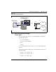
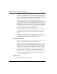

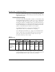
Table Of Contents
- Title Page
- Revision history
- Contents
- About this guide
- Description
- System requirements
- List of ITG ISDN components
- Ordering rules and guidelines
- ITG ISL Trunk card description
- ITG ISL Trunk card physical description
- ISDN Signaling Link
- Dialing plans
- Quality of Service
- Fallback to alternate facilities
- Type of Service
- Fax support
- Remote Access
- Per-call statistics support using RADIUS Client
- SNMP MIB
- Codec profiles
- Security passwords
- ITG Engineering Guidelines
- Introduction
- Network engineering guidelines overview
- ITG traffic engineering
- Configuration of Meridian 1 routes and network translation
- Assess WAN link resources
- QoS Evaluation Process Overview
- Set QoS
- Measure intranet QoS
- Implement QoS in IP networks
- ITG Trunk DSP profile settings
- Post-installation network measurements
- Estimate QoS level
- ITG MAT PC management configuration
- Install and configure ITG ISL Trunk node
- Before you begin
- Installation Procedure Summary
- Create the ITG Trunk Installation Summary Sheet
- Install and cable ITG trunk cards
- Install NTCW84JA Large System I/O Panel 50-Pin filter adapter
- Install NTMF94EA and NTCW84KA cables
- D-channel cabling for the NT0961AA 24-Port ITG Trunk card
- Set NT6D80 MSDL switches
- Install filter and NTND26 cable (for MSDL and DCHIP cards in same Large System equipment row)
- Install filter and NTND26 cable (for MSDL and DCHIP cards in different Large System equipment rows)
- Configure ITG Trunk data on the Meridian 1
- Configure dialing plans within the corporate network
- Configure ITG Trunk data on MAT
- Transmit ITG trunk card configuration data from MAT to the ITG trunk cards
- Set date and time for the ITG ISL Trunk node
- Change the default ITG shell password to maintain access security
- Change default ESN5 prefix for non-ESN5 IP telephony gateways
- Check card software
- Configure MAT Alarm Management to receive SNMP traps from ITG ISL Trunk cards
- Make test calls to the remote ITG nodes
- Upgrade an ITG Trunk 1.0 node to support ISDN signaling trunks
- Upgrade procedure summary
- Before you begin
- Install the DCHIP hardware upgrade kit
- Upgrade the 8-port ITG basic trunk software to ITG ISL trunk software
- Remove ITG 1.0 configuration data from Meridian 1
- Configure the Meridian 1 ITG ISL Trunk data: upgrade considerations
- Verify ROM-BIOS version
- Upgrade Troubleshooting
- OA&M using MAT applications
- OA&M using the ITG shell CLI and overlays
- Maintenance
- Appendix A: Calbe description and NT8D81BA cable replacement
- NTMF94EA E - LAN, T - LAN and Serial Port cable
- NTCW84KA E-LAN, T-LAN, DCH & Serial cable
- NTAG81CA Faceplate Maintenance cable
- NTAG81BA Maintenance Extender cable
- NTCW84EA DCH PC Card Pigtail cable
- NTMF04BA MSDL extension cable
- NTCW84LA and NTCW84MA upgrade cables
- Prevent ground loops on connection to external customer LAN equipment
- Replace cable NT8D81BA with NT8D81AA
- Tools list
- NT8D81BA cable removal procedures
- Appendix B: Environmental and electrical regulatory data
- Appendix C: Subnet mask conversion from CIDR to dotted decimal format
- Appendix D: Configure a Netgear RM356 modem router for remote access
- Index
- Back

Page 140 of
378
ITG Engineering Guidelines
553-3001-202 Standard 1.00 April 2000
gives time for implementation processes to follow through. The planning
thresholds can be set 5% to 15% below the QoS objectives, depending on the
implementation lag time.
Intranet QoS monitoring
To monitor one-way delay and packet loss statistics, you must install a delay
and route monitoring tool, such as ping and traceroute, on the T - LAN
of each ITG site. Each delay monitoring tool will be running continuously,
injecting probe packets to each ITG site about every minute. The amount of
load generated by this is not considered important. At the end of the month,
the hours with the highest one-way delay are noted; within those hours, the
packet loss and standard deviation statistics can be computed.
(See “Measure intranet QoS” on page 114 for information about
implementation of the ping hosts and the use of scripting.)
(See “Obtain QoS measurement tools” on page 118 for information about
where to obtain other more specialized delay and route monitoring tools.)
At the end of the month, the technician can analyze each site’s QoS
information. Table 23 provides a sample.
Declines in QoS can be observed through the comparison of QoS between last
period and current period. If a route does not meet your QoS objective, you
must take immediate action to improve the route’s performance.
Table 23
QoS monitoring
Site pair
One-way delay
Mean+
σ
(ms)
Packet loss
Mean+
σ
(%)
QoS
Last
period
Current
period
Last
period
Current
period
Last
period
Current
period
Objective
Santa Clara/
Richardson
135 166 1 2 Excellent Good Excellent
Santa Clara/
Ottawa
210 155 3 1 Good Excellent Excellent
Etc.