
- LG Software Innovations Coffeemaker User Manual
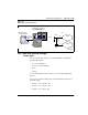
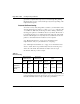
Table Of Contents
- Title Page
- Revision history
- Contents
- About this guide
- Description
- System requirements
- List of ITG ISDN components
- Ordering rules and guidelines
- ITG ISL Trunk card description
- ITG ISL Trunk card physical description
- ISDN Signaling Link
- Dialing plans
- Quality of Service
- Fallback to alternate facilities
- Type of Service
- Fax support
- Remote Access
- Per-call statistics support using RADIUS Client
- SNMP MIB
- Codec profiles
- Security passwords
- ITG Engineering Guidelines
- Introduction
- Network engineering guidelines overview
- ITG traffic engineering
- Configuration of Meridian 1 routes and network translation
- Assess WAN link resources
- QoS Evaluation Process Overview
- Set QoS
- Measure intranet QoS
- Implement QoS in IP networks
- ITG Trunk DSP profile settings
- Post-installation network measurements
- Estimate QoS level
- ITG MAT PC management configuration
- Install and configure ITG ISL Trunk node
- Before you begin
- Installation Procedure Summary
- Create the ITG Trunk Installation Summary Sheet
- Install and cable ITG trunk cards
- Install NTCW84JA Large System I/O Panel 50-Pin filter adapter
- Install NTMF94EA and NTCW84KA cables
- D-channel cabling for the NT0961AA 24-Port ITG Trunk card
- Set NT6D80 MSDL switches
- Install filter and NTND26 cable (for MSDL and DCHIP cards in same Large System equipment row)
- Install filter and NTND26 cable (for MSDL and DCHIP cards in different Large System equipment rows)
- Configure ITG Trunk data on the Meridian 1
- Configure dialing plans within the corporate network
- Configure ITG Trunk data on MAT
- Transmit ITG trunk card configuration data from MAT to the ITG trunk cards
- Set date and time for the ITG ISL Trunk node
- Change the default ITG shell password to maintain access security
- Change default ESN5 prefix for non-ESN5 IP telephony gateways
- Check card software
- Configure MAT Alarm Management to receive SNMP traps from ITG ISL Trunk cards
- Make test calls to the remote ITG nodes
- Upgrade an ITG Trunk 1.0 node to support ISDN signaling trunks
- Upgrade procedure summary
- Before you begin
- Install the DCHIP hardware upgrade kit
- Upgrade the 8-port ITG basic trunk software to ITG ISL trunk software
- Remove ITG 1.0 configuration data from Meridian 1
- Configure the Meridian 1 ITG ISL Trunk data: upgrade considerations
- Verify ROM-BIOS version
- Upgrade Troubleshooting
- OA&M using MAT applications
- OA&M using the ITG shell CLI and overlays
- Maintenance
- Appendix A: Calbe description and NT8D81BA cable replacement
- NTMF94EA E - LAN, T - LAN and Serial Port cable
- NTCW84KA E-LAN, T-LAN, DCH & Serial cable
- NTAG81CA Faceplate Maintenance cable
- NTAG81BA Maintenance Extender cable
- NTCW84EA DCH PC Card Pigtail cable
- NTMF04BA MSDL extension cable
- NTCW84LA and NTCW84MA upgrade cables
- Prevent ground loops on connection to external customer LAN equipment
- Replace cable NT8D81BA with NT8D81AA
- Tools list
- NT8D81BA cable removal procedures
- Appendix B: Environmental and electrical regulatory data
- Appendix C: Subnet mask conversion from CIDR to dotted decimal format
- Appendix D: Configure a Netgear RM356 modem router for remote access
- Index
- Back

Page 134 of
378
ITG Engineering Guidelines
553-3001-202 Standard 1.00 April 2000
bandwidth use of the G.711 codec series, it is recommended that no more than
two ITG cards share the same LAN collision domain in a G.711-only ITG
network.
If you use a mixed codec ITG network or use a non-default payload size or
fax settings, then you must use the LAN bandwidth consumption in Table 5
to estimate the amount of LAN bandwidth used by each card. It is
recommended that you do not use the 10Mbit/s collision domain beyond
25-30% at the peak.
If the uplink from the T-LAN hub (either passive or switched) to the router is
10Mbit/s, then the maximum number of ITG cards allowed per hub is equal
to the limit described in the previous paragraph. If the uplink is 100Mbit/s,
then the maximum number of ITG cards allowed on the switched hub is
subject to the limits described in the “Leader Card Real Time Engineering”
section of this document.
You may want to consider implementing LAN resiliency. This is achieved by
provisioning Leader and Follower cards on separate Ethernet hubs (but
served by the same router). In this design the ITG node can provide voice
services when one of the hubs fails.
The ITG node and the T-LAN router should be placed as close to the WAN
backbone as possible, again to minimize the number of router hops, segregate
constant bit-rate Voice over IP traffic from bursty LAN traffic, and simplify
the end-to-end Quality of Service engineering for packet delay, jitter, and
packet loss. If an access router separates the ITG node from the WAN router,
there should be a high-speed link (e.g., Fast Ethernet, FDDI, SONET, OC-3c,
ATM STS-3c) between the access router and the WAN backbone router.
Setting the Quality of Service threshold for fallback routing
The Quality of Service thresholds for fallback routing are configured in the
MAT application. A threshold is configured for the “Receive fall back
threshold” as well as the “Transmit fall back threshold.” The available
thresholds are: “Excellent, Good, Fair, and Poor.”
Basic setup of the ITG system
Figure 19 shows an example of a basic recommended ITG system setup, with
separate voice and management networks. This is for illustrative purposes,
and is not necessarily the setup you must use.