
- LG Software Innovations Coffeemaker User Manual
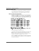
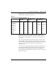
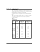
Table Of Contents
- Title Page
- Revision history
- Contents
- About this guide
- Description
- System requirements
- List of ITG ISDN components
- Ordering rules and guidelines
- ITG ISL Trunk card description
- ITG ISL Trunk card physical description
- ISDN Signaling Link
- Dialing plans
- Quality of Service
- Fallback to alternate facilities
- Type of Service
- Fax support
- Remote Access
- Per-call statistics support using RADIUS Client
- SNMP MIB
- Codec profiles
- Security passwords
- ITG Engineering Guidelines
- Introduction
- Network engineering guidelines overview
- ITG traffic engineering
- Configuration of Meridian 1 routes and network translation
- Assess WAN link resources
- QoS Evaluation Process Overview
- Set QoS
- Measure intranet QoS
- Implement QoS in IP networks
- ITG Trunk DSP profile settings
- Post-installation network measurements
- Estimate QoS level
- ITG MAT PC management configuration
- Install and configure ITG ISL Trunk node
- Before you begin
- Installation Procedure Summary
- Create the ITG Trunk Installation Summary Sheet
- Install and cable ITG trunk cards
- Install NTCW84JA Large System I/O Panel 50-Pin filter adapter
- Install NTMF94EA and NTCW84KA cables
- D-channel cabling for the NT0961AA 24-Port ITG Trunk card
- Set NT6D80 MSDL switches
- Install filter and NTND26 cable (for MSDL and DCHIP cards in same Large System equipment row)
- Install filter and NTND26 cable (for MSDL and DCHIP cards in different Large System equipment rows)
- Configure ITG Trunk data on the Meridian 1
- Configure dialing plans within the corporate network
- Configure ITG Trunk data on MAT
- Transmit ITG trunk card configuration data from MAT to the ITG trunk cards
- Set date and time for the ITG ISL Trunk node
- Change the default ITG shell password to maintain access security
- Change default ESN5 prefix for non-ESN5 IP telephony gateways
- Check card software
- Configure MAT Alarm Management to receive SNMP traps from ITG ISL Trunk cards
- Make test calls to the remote ITG nodes
- Upgrade an ITG Trunk 1.0 node to support ISDN signaling trunks
- Upgrade procedure summary
- Before you begin
- Install the DCHIP hardware upgrade kit
- Upgrade the 8-port ITG basic trunk software to ITG ISL trunk software
- Remove ITG 1.0 configuration data from Meridian 1
- Configure the Meridian 1 ITG ISL Trunk data: upgrade considerations
- Verify ROM-BIOS version
- Upgrade Troubleshooting
- OA&M using MAT applications
- OA&M using the ITG shell CLI and overlays
- Maintenance
- Appendix A: Calbe description and NT8D81BA cable replacement
- NTMF94EA E - LAN, T - LAN and Serial Port cable
- NTCW84KA E-LAN, T-LAN, DCH & Serial cable
- NTAG81CA Faceplate Maintenance cable
- NTAG81BA Maintenance Extender cable
- NTCW84EA DCH PC Card Pigtail cable
- NTMF04BA MSDL extension cable
- NTCW84LA and NTCW84MA upgrade cables
- Prevent ground loops on connection to external customer LAN equipment
- Replace cable NT8D81BA with NT8D81AA
- Tools list
- NT8D81BA cable removal procedures
- Appendix B: Environmental and electrical regulatory data
- Appendix C: Subnet mask conversion from CIDR to dotted decimal format
- Appendix D: Configure a Netgear RM356 modem router for remote access
- Index
- Back

ITG Engineering Guidelines Page 117 of
378
ITG Trunk 2.0 ISDN Signaling Link (ISL) Description, Installation and Operation
Table 20 provides a sample measurement of network delay and packet loss
for the G.729A codec between various nodes.
Table 20
Sample Measurement Results for G.729A codec
As an example, the delay and loss pair of traffic from Santa Clara to
Richardson (171 ms and 1.5%) will meet “excellent” criterion, but their
counter part with standard deviation (179 ms and 2.1%) can achieve only
“good” QoS.
Since the algorithm implemented in ITG will calculate mean only and not
standard deviation, it will confirm the “excellent” rating (if the objective is
set for excellent, it will not fallback to alternate facilities), but the customer
will have up to 50% chance to experience a service level inferior to
“excellent” level.
As a contrast, the site pair Santa Clara/Ottawa which has both QoS levels of
mean and mean+σ falling in the excellent region. The customer will have
more confidence that (better than 84% chance under the assumption of
Normal distribution) during peak traffic period, the “excellent” service level
is likely to be upheld.
Destination pair
Measured One way
delay (ms)
Measured Packet
loss (%)
Expected QoS level
(See page 143)
Mean
Mean+
σ
Mean
Mean+
σ
Mean
Mean+
σ
Santa Clara/
Richardson
171 179 1.5 2.1 Excellent Good
Santa Clara/
Ottawa
120 132 1.3 1.6 Excellent Excellent
Santa Clara/
To k y o
190 210 2.1 2.3 Good Good
Richardson/
Ottawa
220 235 2.4 2.7 Good Good
Richardson/
To k y o
305 345 2.2 2.6 Good Fair
Ottawa/
To k yo
260 286 2.4 2.8 Good Fair