
- LG Software Innovations Coffeemaker User Manual
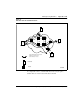

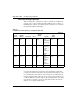

Table Of Contents
- Title Page
- Revision history
- Contents
- About this guide
- Description
- System requirements
- List of ITG ISDN components
- Ordering rules and guidelines
- ITG ISL Trunk card description
- ITG ISL Trunk card physical description
- ISDN Signaling Link
- Dialing plans
- Quality of Service
- Fallback to alternate facilities
- Type of Service
- Fax support
- Remote Access
- Per-call statistics support using RADIUS Client
- SNMP MIB
- Codec profiles
- Security passwords
- ITG Engineering Guidelines
- Introduction
- Network engineering guidelines overview
- ITG traffic engineering
- Configuration of Meridian 1 routes and network translation
- Assess WAN link resources
- QoS Evaluation Process Overview
- Set QoS
- Measure intranet QoS
- Implement QoS in IP networks
- ITG Trunk DSP profile settings
- Post-installation network measurements
- Estimate QoS level
- ITG MAT PC management configuration
- Install and configure ITG ISL Trunk node
- Before you begin
- Installation Procedure Summary
- Create the ITG Trunk Installation Summary Sheet
- Install and cable ITG trunk cards
- Install NTCW84JA Large System I/O Panel 50-Pin filter adapter
- Install NTMF94EA and NTCW84KA cables
- D-channel cabling for the NT0961AA 24-Port ITG Trunk card
- Set NT6D80 MSDL switches
- Install filter and NTND26 cable (for MSDL and DCHIP cards in same Large System equipment row)
- Install filter and NTND26 cable (for MSDL and DCHIP cards in different Large System equipment rows)
- Configure ITG Trunk data on the Meridian 1
- Configure dialing plans within the corporate network
- Configure ITG Trunk data on MAT
- Transmit ITG trunk card configuration data from MAT to the ITG trunk cards
- Set date and time for the ITG ISL Trunk node
- Change the default ITG shell password to maintain access security
- Change default ESN5 prefix for non-ESN5 IP telephony gateways
- Check card software
- Configure MAT Alarm Management to receive SNMP traps from ITG ISL Trunk cards
- Make test calls to the remote ITG nodes
- Upgrade an ITG Trunk 1.0 node to support ISDN signaling trunks
- Upgrade procedure summary
- Before you begin
- Install the DCHIP hardware upgrade kit
- Upgrade the 8-port ITG basic trunk software to ITG ISL trunk software
- Remove ITG 1.0 configuration data from Meridian 1
- Configure the Meridian 1 ITG ISL Trunk data: upgrade considerations
- Verify ROM-BIOS version
- Upgrade Troubleshooting
- OA&M using MAT applications
- OA&M using the ITG shell CLI and overlays
- Maintenance
- Appendix A: Calbe description and NT8D81BA cable replacement
- NTMF94EA E - LAN, T - LAN and Serial Port cable
- NTCW84KA E-LAN, T-LAN, DCH & Serial cable
- NTAG81CA Faceplate Maintenance cable
- NTAG81BA Maintenance Extender cable
- NTCW84EA DCH PC Card Pigtail cable
- NTMF04BA MSDL extension cable
- NTCW84LA and NTCW84MA upgrade cables
- Prevent ground loops on connection to external customer LAN equipment
- Replace cable NT8D81BA with NT8D81AA
- Tools list
- NT8D81BA cable removal procedures
- Appendix B: Environmental and electrical regulatory data
- Appendix C: Subnet mask conversion from CIDR to dotted decimal format
- Appendix D: Configure a Netgear RM356 modem router for remote access
- Index
- Back

Page 102 of
378
ITG Engineering Guidelines
553-3001-202 Standard 1.00 April 2000
be consistent with the dimensioning considerations (see “ITG traffic
engineering” on page 76), obtain the busy period (e.g. peak hour) utilization
of the trunk. Also, because WAN links are full-duplex and that data services
exhibit asymmetric traffic behavior, obtain the utilization of the link
representing traffic flowing in the heavier direction.
The third step is to assess how much spare capacity is available. Enterprise
intranets are subject to capacity planning policies that ensure that capacity use
remains below some determined utilization level. For example, a planning
policy might state that the utilization of a 56 kbit/s link during the peak hour
must not exceed 50%; for a T1 link, the threshold is higher, say at 80%. The
carrying capacity of the 56 kbit/s link would be 28 kbit/s, and for the T1
1.2288 Mbit/s. In some organizations the thresholds can be lower than that
used in this example; in the event of link failures, there needs to be spare
capacity for traffic to be re-routed.
Some WAN links may actually be provisioned on top of layer 2 services such
as Frame Relay and ATM; the router-to-router link is actually a virtual circuit,
which is subject not only to a physical capacity, but also a “logical capacity”
limit. The technician needs to obtain, in addition to the physical link capacity,
the QoS parameters, the important ones being CIR (committed information
rate) for Frame Relay, and MCR (maximum cell rate) for ATM.
The difference between the current capacity and its allowable limit is the
available capacity. For example a T1 link utilized at 48% during the peak
hour, with a planning limit of 80% had an available capacity of about 492
kbit/s.
Estimate network loading
caused by
ITG traffic
At this point, the technician has enough information to "load" the ITG traffic
on the intranet. Figure 13 illustrates how this is done on an individual link.
Suppose the intranet has a topology as shown in Figure 13, and you want to
predict the amount of traffic on a specific link, R4-R5. From the “ITG traffic
engineering” section and measurements, the R4-R5 link is
expected to support the Santa Clara/Richardson, Santa Clara/Tokyo and the
Ottawa/Tokyo traffic flows; the other ITG traffic flows do not route over
R4-R5. The summation of the three flows yields 93 CCS or 24 kbit/s as the
incremental traffic that R4-R5 will need to support.