
- LG Software Innovations Coffeemaker User Manual
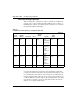
Table Of Contents
- Title Page
- Revision history
- Contents
- About this guide
- Description
- System requirements
- List of ITG ISDN components
- Ordering rules and guidelines
- ITG ISL Trunk card description
- ITG ISL Trunk card physical description
- ISDN Signaling Link
- Dialing plans
- Quality of Service
- Fallback to alternate facilities
- Type of Service
- Fax support
- Remote Access
- Per-call statistics support using RADIUS Client
- SNMP MIB
- Codec profiles
- Security passwords
- ITG Engineering Guidelines
- Introduction
- Network engineering guidelines overview
- ITG traffic engineering
- Configuration of Meridian 1 routes and network translation
- Assess WAN link resources
- QoS Evaluation Process Overview
- Set QoS
- Measure intranet QoS
- Implement QoS in IP networks
- ITG Trunk DSP profile settings
- Post-installation network measurements
- Estimate QoS level
- ITG MAT PC management configuration
- Install and configure ITG ISL Trunk node
- Before you begin
- Installation Procedure Summary
- Create the ITG Trunk Installation Summary Sheet
- Install and cable ITG trunk cards
- Install NTCW84JA Large System I/O Panel 50-Pin filter adapter
- Install NTMF94EA and NTCW84KA cables
- D-channel cabling for the NT0961AA 24-Port ITG Trunk card
- Set NT6D80 MSDL switches
- Install filter and NTND26 cable (for MSDL and DCHIP cards in same Large System equipment row)
- Install filter and NTND26 cable (for MSDL and DCHIP cards in different Large System equipment rows)
- Configure ITG Trunk data on the Meridian 1
- Configure dialing plans within the corporate network
- Configure ITG Trunk data on MAT
- Transmit ITG trunk card configuration data from MAT to the ITG trunk cards
- Set date and time for the ITG ISL Trunk node
- Change the default ITG shell password to maintain access security
- Change default ESN5 prefix for non-ESN5 IP telephony gateways
- Check card software
- Configure MAT Alarm Management to receive SNMP traps from ITG ISL Trunk cards
- Make test calls to the remote ITG nodes
- Upgrade an ITG Trunk 1.0 node to support ISDN signaling trunks
- Upgrade procedure summary
- Before you begin
- Install the DCHIP hardware upgrade kit
- Upgrade the 8-port ITG basic trunk software to ITG ISL trunk software
- Remove ITG 1.0 configuration data from Meridian 1
- Configure the Meridian 1 ITG ISL Trunk data: upgrade considerations
- Verify ROM-BIOS version
- Upgrade Troubleshooting
- OA&M using MAT applications
- OA&M using the ITG shell CLI and overlays
- Maintenance
- Appendix A: Calbe description and NT8D81BA cable replacement
- NTMF94EA E - LAN, T - LAN and Serial Port cable
- NTCW84KA E-LAN, T-LAN, DCH & Serial cable
- NTAG81CA Faceplate Maintenance cable
- NTAG81BA Maintenance Extender cable
- NTCW84EA DCH PC Card Pigtail cable
- NTMF04BA MSDL extension cable
- NTCW84LA and NTCW84MA upgrade cables
- Prevent ground loops on connection to external customer LAN equipment
- Replace cable NT8D81BA with NT8D81AA
- Tools list
- NT8D81BA cable removal procedures
- Appendix B: Environmental and electrical regulatory data
- Appendix C: Subnet mask conversion from CIDR to dotted decimal format
- Appendix D: Configure a Netgear RM356 modem router for remote access
- Index
- Back

ITG Engineering Guidelines Page 101 of
378
ITG Trunk 2.0 ISDN Signaling Link (ISL) Description, Installation and Operation
The bandwidth requirement calculation would be = (40/36)*11.2 +
(14/36)*33.6 = 25.51 kbit/s, where 14 CCS is the larger of two fax traffic
parcels (14 CCS as compared to. 6 CCS). After adjusting for peaking, the
incremental data rate on WAN for this route is 33.2 kbit/s. Compare this
number with 24.3 kbit/s when all 60 CCS is voice traffic, it appears that the
reduction in CCS due to one-way fax traffic (20 CCS as compared to 14 CCS)
will not compensate for higher bandwidth requirement of a fax as compared
to. voice call (33.7 kbit/s as compared to. 11.2 kbit/s) in this example.
The example in this section deals with nodal traffic calculation in both
T-LAN and WAN. It indicates incremental bandwidth requirement to handle
voice on data networks.
Assess WAN link resources
For most installations, ITG traffic will be routed over WAN links within the
intranet. WAN links are the most expensive repeating expenses in the
network and they often are the source of capacity problems in the network.
Unlike LAN bandwidth, which is virtually free and easily implemented,
WAN links, especially inter-LATA and international links take time to obtain
financial approval, provision and upgrade. For these reasons, it is important
to determine the state of WAN links in the intranet before installing the ITG
network.
Each voice conversation, (G.729 Annex AB codec, 30 ms payload) consumes
11.2 kbit/s of bandwidth or 18.6 kbit/s with silence suppression disabled for
each link that it traverses in the intranet; a DS0 64 kbit/s WAN link would
support 5 simultaneous telephone conversations with silence suppression
enabled, or 2 simultaneous telephone conversations with silence suppression
disabled.
Link utilization
The starting point of this assessment is to obtain a current topology map and
link utilization report of the intranet. A visual inspection of the topology map
should reveal which WAN links are likely to be used to deliver ITG traffic.
Alternately use the tool (see “Measure intranet QoS” on
page 114).
The next step is to find out the current utilization of those links. Note the
reporting window that appears in the link utilization report. For example, the
link utilization can be averaged over a week, a day, or one hour. In order to