C H A P T E R 2 Provisioning The Provisioning Management chapter of the Cisco Internet OSS for VoIP: Infrastructure Manager (Cisco VoIP: Infrastructure Manager) Solution is the second chapter in a four chapter Cisco VoIP: Infrastructure Manager Solution document. Provisioning management, in the context of this Solution, deals with the provisioning of network elements and the management of those configuration files.
Chapter 2 Provisioning Overview Target Market The applications and devices described in this document are positioned for service provider scale, VoIP networks. Although many of the applications can be deployed in enterprises and smaller scale networks, the solution suite referred to in this Solution guide is aimed at the large carriers and providers of VoIP network bandwidth and services.
Chapter 2 Provisioning Solution Architecture Solution Architecture Open Packet Telephony Overview As an introduction to the Cisco VoIP: Infrastructure Manager Solution’s provisioning component applications and devices, the following overview of the emerging technology of distributed packet telephony is presented. Telephony is no longer solely the domain of Public Switched Telephone Networks (PSTNs).
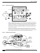
Chapter 2 Provisioning Solution Architecture Figure 2-1 MGCP Packet Voice Network Media Gateway Controller (MGC) Signaling and control MGC VoP network Call control MGCP, H. 248, Megaco, SCTP, signaling backhaul,.... IP network Circuit Core/TDM SS7 network STP STP Class 4 V CPE Media Gateway IP, PNNI, ... Bearer PBX 84405 Media Gateway PBX V V Figure 2-2 depicts an H.323-based network for Voice Infrastructure and Applications (VIA) Solution.
Chapter 2 Provisioning Solution Architecture Virtual Entities in the Network The requirements for coordinated element management are extensive. For instance, the media gateway and MGC must be synchronized regarding the voice endpoints. Although the MGC has a concept of a trunk, this concept is unknown to the media gateway that has the actual resources (TDM endpoints, ports) that constitute the trunk.
Chapter 2 Provisioning Solution Architecture Figure 2-4 Other Virtual Network Entities Virtual SS7 Gateway Virtual zone Virtual region PGW 2200 SS7 DGK GK STP Ingress ITSP DGK V V GK V V V V V V 84410 Trunk GK V V AS5xxx The concept of virtual network entities is key to the management of packet voice networks. Cisco PTC and it's companion provisioning management applications readily support this concept.
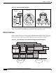
Chapter 2 Provisioning Solution Architecture IOSS Provisioning Component Architecture Figure 2-6 depicts the proposed Provisioning Management Solution for OPT networks, as applied to an H.323-based global long-distance network. The key component is the Cisco Packet Telephony Center (Cisco PTC), which provides for overall configuration management of the OPT network and realizes the virtual entities as discussed. A module within Cisco PTC, called Cisco VRC, provides for H.323 dial-plan management.
Chapter 2 Provisioning Solution Architecture Figure 2-6 Provisioning Management Component Devices Customer provided OSS components Packet Telephony Center Voice Services CNS Intelligence Engine Gateways Gatekeepers Cisco MGC Node Manager Voice Services Provisioning Tool PGW 2200 84412 Cisco Voice Routing Center Functional Description Cisco PTC oversees the entire network.
Chapter 2 Provisioning Configuration and Provisioning Solution Components The gateways and gatekeepers that comprise the H.323 voice network send fault and performance data directly to the fault and performance processing applications (Cisco CNS Notification Engine, Cisco Info Center, and Cisco CNS Performance Engine). Protocols for transporting this data include SNMP, Syslog, and RADIUS.
Chapter 2 Provisioning Configuration and Provisioning Solution Components Cisco Voice Routing Center Cisco VRC is a GUI-based network management tool specifically designed for managing dial plans in a Voice over IP (VoIP) network. Cisco VRC, version 1.1, is targeted for H.323-based networks. H.323 VoIP dial plans are statically configured and managed on gateway and gatekeeper platforms. The infrastructure of a typical H.323 VoIP network includes gateways and gatekeepers.
Chapter 2 Provisioning Configuration and Provisioning Solution Components Figure 2-7 PGW 2200 and MGC Node Manager Details End user Xterminal Cisco PGW 2200 Catalyst MGC Node Manager MGC Node Manager Presentation Server Management Server Host/ SLT detail Active Host Standby Host Checkpointing Signaling Control network Link set A To Gateways and other Cisco PGW 2200 nodes SLT SS7 A or F links Link set B 84413 SLT CMNM Features The most common Cisco EMF installation includes plug-in modules r
Chapter 2 Provisioning Configuration and Provisioning Solution Components CMNM Configuration You can open the following configuration tools from CMNM: • Voice Services Provisioning Tool (VSPT) • CiscoView, which allows you to configure and monitor the Cisco SLT and the LAN switch (Cisco Catalyst 2900, 5500 and 6509) devices.
Chapter 2 Provisioning Configuration and Provisioning Solution Components Voice Services Provisioning Tool Provisioning with the VSPT is the process of preparing a Cisco Media PGW 2200 to communicate with an SS7 network, with Cisco media gateways, and with the other components of an OPT Solution. The VSPT application provides an easy to use GUI to provision the Cisco PGW 2200. VSPT can be deployed as an integrated component of the CMNM or as a standalone application.
Chapter 2 Provisioning Configuration and Provisioning Solution Components Cisco CNS Intelligence Engine Cisco CNS Intelligence Engine and Cisco CNS Bus Technology The Cisco CNS Intelligence Engine (Cisco CNS IE2100 Series) is a network management appliance that acts as a configuration service for automating the deployment and management of network devices and services.
Chapter 2 Provisioning Step by Step Installation and Initial Configuration Step by Step Installation and Initial Configuration Overview of Installation The order of installation follows the plan below: 1. Install and configure the Cisco CNS IE2100 appliance with a subnet IP address. 2. On the CMNM host, install the Cisco MGC Node Manager application, including: a. Voice Services Provisioning Tool. b. CEMF 3.2. c. CiscoView upgrade if necessary. d. Cisco MGC Node Manager (server). 3.
Chapter 2 Provisioning Step by Step Installation and Initial Configuration Installation Overview The installation procedure for the Cisco CNS Configuration Registrar is straightforward. The software is installed and configured through a console connection to the serial port. The console connection parameters are the same as for other Cisco IOS devices, that is: Step 1 • 9600 baud • Parity: 8/None • Stop bits: 1.
Chapter 2 Provisioning Step by Step Installation and Initial Configuration zone(2): 32748 pages. zone HighMem has max 255 cached pages. hm, page 01000000 reserved twice. Kernel command line: auto BOOT_IMAGE=linux ro root=806 BOOT_FILE=/boot/vmlinuz-2.4.2-2 console=ttyS0,9600n8 Initializing CPU#0 Detected 1130.197 MHz processor. Console: color VGA+ 80x25 Calibrating delay loop... 2254.
Chapter 2 Provisioning Step by Step Installation and Initial Configuration Uniform Multi-Platform E-IDE driver Revision: 6.
Chapter 2 Provisioning Step by Step Installation and Initial Configuration Partition check: sda: sda1 sda2 < sda5 sda6 sda7 sda8 sda9 sda10 sda11 sda12 sda13 > VFS: Mounted root (ext2 filesystem) readonly. change_root: old root has d_count=3 Trying to unmount old root ... okay Freeing unused kernel memory: 236k freed INIT: version 2.78 booting Welcome to Red Hat Linux Press 'I' to enter interactive startup.
Chapter 2 Provisioning Step by Step Installation and Initial Configuration Starting system logger: [OK] Starting kernel logger: [OK] Starting portmapper: [OK] Starting NFS file locking services: Starting NFS statd: [OK] Starting keytable: [OK] Initializing random number generator: [OK] Mounting other filesystems: [OK] Starting automount:[OK] Starting atd: [OK] Starting sshd: [OK] Starting xinetd: [OK] Starting lpd: No Printers Defined[OK] Starting sendmail: [OK] Starting console mouse services: [OK] Star
Chapter 2 Provisioning Step by Step Installation and Initial Configuration Enter the Secondary DNS Server IP address: 171.68.226.120 Enter the Country Code: us Enter the Company Code: cisco Enter the ConfigService AdminID: csadmin Enter the ConfigService password: ****** Re-Enter the ConfigService password: ****** Enter the NSM Directives: This field requires an input.
Chapter 2 Provisioning Step by Step Installation and Initial Configuration Company Code: cisco ConfigService AdminID: csadmin ConfigService password: ****** NSM Directives: default:// Event Gateway Debug Log (y/n): n # of Event Gateways N for serving 500 x N devices: 1 CNS Event Bus Network Parameter: ie-tme CNS Event Bus Service Parameter: 7500 Re-configure IMGW (y/n): n Commit changes (y/n): y Update administrator info ... Shutdown servers ... Configure network ... eepro100.c:v1.
Chapter 2 Provisioning Step by Step Installation and Initial Configuration Cisco Intelligence Engine 2110 Cisco Configuration Registrar (tm) Software, Version 1.2(1a) [ming_cao-ie2100_1_2_fcs.p1 100] Copyright (c) 2001, 2002 by cisco Systems, Inc. Compiled Tue 05-Mar-2002 20:37 by ming_cao [root@ie-tme /root]# Refer to the Cisco CNS Configuration Registrar Installation Guide for more details. The “Related Documents” section provides a URL to the Cisco CNS Configuration Registrar documentation.
Chapter 2 Provisioning Step by Step Installation and Initial Configuration The variable parameters are the IP address of the Cisco CNS IE2100 appliance (172.19.49.20), the communication port (80), the keep alive time (100 seconds), and the retry count (30). There are several ways for this to happen. The method of choice in this chapter is to do it through the Cisco PTC Topology Manager.
Chapter 2 Provisioning Step by Step Installation and Initial Configuration 2. CMNM 2.3.1 on the second CD, including: a. the CMNM Element Managers that work with Cisco EMF. b. Cisco MGC Node Manager for provisioning the Cisco Media Gateway Controller. c. CiscoView 5.1, installed automatically when CMNM is installed (management interface for the Cisco SLT). 3. CiscoWorks on the third CD. You will also need VSPT version 2.3.1 with patch P01 and Release Notes available from: http://www.cisco.
Chapter 2 Provisioning Step by Step Installation and Initial Configuration The following steps install the recommended Patch Cluster that has been downloaded to the /opt/patches directory (create this directory first) on the Cisco PTC machine. Step 1 Go to the /opt directory: ptc-tme# cd /opt Step 2 Create the patches directory: ptc-tme# mkdir patches Step 3 Go to the /patches directory: ptc-tme# cd patches Step 4 List the contents of the patches directory: ptc-tme# ls 8_Recommended.
Chapter 2 Provisioning Step by Step Installation and Initial Configuration *WARNING* SYSTEMS WITH LIMITED DISK SPACE SHOULD *NOT* INSTALL PATCHES: With or without using the save option, the patch installation process will still require some amount of disk space for installation and administrative tasks in the /, /usr, /var, or /opt partitions where patches are typically installed.
Chapter 2 Provisioning Step by Step Installation and Initial Configuration 110554-01, 109472-07, 109740-04, 109742-04, 109060-02, 11018 2-01, 111537-01, 109062-01, 110186-01, 110186-02, 110595-01, 110932-01, 111054-02, 109181-04, 109279-19, 109904-05, 109906-06, 10995 4-01, 110098-01, 110383-02, 111035-01, 111884-02, 111919-04, 112334-02 Requires: 108987-09, 111111-03, 111293-01, 111310-01, , I incompatibles: 109079-01 Packages: SUNWkvmx, SUNWkvm, SUNWcarx, SUNWcar, SUNWcsu, SUNWcsr, SUNWcslx, SUNWcsl
Chapter 2 Provisioning Step by Step Installation and Initial Configuration Step 8 Provide answers to the questions at the end of the form, then click Enter Form. To update a Cisco EMF license currently in use (for example, if you wish to extend an evaluation license or convert an evaluation system to a proper installation with a permanent license) refer to the Cisco EMF Installation and Administration Guide at: http://www.cisco.com/univercd/cc/td/doc/product/rtrmgmt/cemf/3_2/install/license.
Chapter 2 Provisioning Step by Step Installation and Initial Configuration cmnm-pri# mkdir tmp cmnm-pri# cd tmp cmnm-pri# ls CSCOvspt-2.3.1.tar Step 2 Untar the contents of the CSCOvspt-2.3.1.tar file: cmnm-pri# tar -xvof CSCOvspt-2.3.1.tar x ., 0 bytes, 0 tape blocks x ./version, 343 bytes, 1 tape blocks x ./README_FIRST.txt, 5545 bytes, 11 tape blocks x ./README_NOTES.txt, 20779 bytes, 41 tape blocks x ./jre, 0 bytes, 0 tape blocks x .
Chapter 2 Provisioning Step by Step Installation and Initial Configuration Step 5 You are asked to read a description of the application and then the license agreement whose output is omitted here. At the end of the license agreement, you must accept the agreement in order to continue. Then follow the on screen prompts. The default answers are in block parentheses. If you want to accept the default response, just click Enter: Step 6 Enter “I accept the terms of the license agreement.
Chapter 2 Provisioning Step by Step Installation and Initial Configuration Cisco Voice Services Provisioning Tool Destination: /opt/CSCOvsp23 Installed Features: Program Files (26.9MB) Data Files (162KB) 1. Exit What would you like to do [1]? 1 Cisco Voice Services Provisioning Tool installation is complete. __________________________________________________________________ Step 8 After the main image is installed, do the same with the patch file for VSPT: cmnm-pri# ls CSCOvspt-2.3.1.
Chapter 2 Provisioning Step by Step Installation and Initial Configuration ----------------------------------Installing Patch 01 to CSCOvsp23 --------------------------------------------------------------------Backing up file to be patched ----------------------------------/var/sadm/pkg/CSCOvsp23/pkginfo to ?---------------output suppressed---------------------? Processing package instance from Cisco Voice Services Provisioning Tool (sparc) 2.3(1) Cisco Systems, Inc.
Chapter 2 Provisioning Step by Step Installation and Initial Configuration Checking for Package Install Step 11 Check to ensure the entire package was installed: cmnm-pri# pkginfo -l CSCOvsp23 PKGINST: NAME: CATEGORY: ARCH: CSCOvsp23 Cisco Voice Services Provisioning Tool application sparc VERSION: 2.3(1) BASEDIR: /opt/CSCOvsp23 VENDOR: Cisco Systems, Inc.
Chapter 2 Provisioning Step by Step Installation and Initial Configuration CEMF Manager (sparc) 3.2 Cisco Systems, Inc.
Chapter 2 Provisioning Step by Step Installation and Initial Configuration ObjectStore has not been found on the system. ObjectStore needs to be installed. Is this correct [y] [y,n,?] CEMF Manager Installation To gain extra performance ObjectStore can be configured to use a raw partition to store its databases. Choosing this option will require ObjectStore to be correctly configured before any attempt to start CEMF Manager can be made.
Chapter 2 Provisioning Step by Step Installation and Initial Configuration * Alternatively you can use an existing FlexLM daemon if one is already running on your system. Note If you answer no to the following question, you should be able to provide a valid path for your licence file. It is then copied to the /opt/cemf/config/licenses directory.
Chapter 2 Provisioning Step by Step Installation and Initial Configuration /opt/cemf/Orbix2000/bin/itconfig_rep /opt/cemf/Orbix2000/bin/itevent /opt/cemf/Orbix2000/bin/itifr /opt/cemf/Orbix2000/bin/itkdm /opt/cemf/Orbix2000/bin/itlocator ?-----------output suppressed------------------------? /opt/cemf/db/pollerServer.adb /opt/cemf/db/serviceMgrServer.adb /opt/cemf/db/statusPropagationRecalculator.
Chapter 2 Provisioning Step by Step Installation and Initial Configuration Step 1 List the contents of the Patch directory: cmnm-pri# ls Step 2 -rw-r--r-- 1 root other 1280455 Sep 26 09:31 CEMF3.2P3.2.tar.Z -rw-r--r-- 1 root other 145691565 Sep 26 09:31 CEMF3.2P3.tar.Z Uncompress the Patch files: cmnm-pri# uncompress * Step 3 Untar Patch P3: cmnm-pri# tar -xvof CEMF3.2P3.tar x ., 0 bytes, 0 tape blocks x ./CEMF_3.2_PATCH_3, 0 bytes, 0 tape blocks x ./CEMF_3.
Chapter 2 Provisioning Step by Step Installation and Initial Configuration Step 7 Invoke the CEMF installation script: cmnm-pri# ./cemfinstall INSTALL PACKAGE =============== 1) CEMF Server 3.2 Patch 170003-10 2) CEMF Client 3.2 Patch 170103-10 - Not Installed q) Quit Which package do you wish to install? (Def:1) [?,q] 1 Option "CEMF Server 3.2 Patch 170003-10" chosen. Installing package(s) "CSCOcemfm". CEMF Manager system not running. There are no previous patches to remove.
Chapter 2 Provisioning Step by Step Installation and Initial Configuration Step 11 Invoke the CEMF installation script: cmnm-pri# ./cemfinstall INSTALL PACKAGE =============== 1) CEMF Server 3.2 Patch 190302-01 2) CEMF Client 3.2 Patch 200302-01 - Not Installed q) Quit Which package do you wish to install? (Def:1) [?,q] 1 Option "CEMF Server 3.2 Patch 190302-01" chosen. Installing package(s) "CSCOcemfm". CEMF Manager system not running. Checking installed patches...
Chapter 2 Provisioning Step by Step Installation and Initial Configuration Installing the Cisco MGC Node Manager Step 1 Before installing CMNM, ensure CEMF is running: cmnm-pri# cd /opt/cemf cmnm-pri# bin/cemf query CEMF Manager 3.
Chapter 2 Provisioning Step by Step Installation and Initial Configuration 9151 /opt/cemf/Orbix2000/orbix_art/1.2/bin/sc42/itlocator -ORBname locator run 9139 nbinterface 9153 /opt/cemf/Orbix2000/orbix_art/2.0/bin/itlocator run -ORBdomain_name CEMF_2.0 -O 9152 /bin/sh /opt/cemf/bin/cgw_wrap_itact 9182 /opt/cemf/Orbix2000/orbix_art/1.2/bin/sc42/itactivator - ORBname activator run 9185 /opt/cemf/Orbix2000/orbix_art/1.2/bin/sc42/itnaming 9154 /opt/cemf/Orbix2000/orbix_art/2.
Chapter 2 Provisioning Step by Step Installation and Initial Configuration Setup has detected that the CEMF Manager software is installed. Do you wish to install the CSCOcmnm Manager software. [y/n]: y It is recommended that your databases are backed up before running this command. Have your databases been backed up [y/n]: [n] y Note If your install is brand new, there are no databases to backup, so you can answer y to the above query and the install continues.
Chapter 2 Provisioning Step by Step Installation and Initial Configuration [verifying class ] Installation of was successful. The following packages are available: 1 CSCOcmnm Cisco MGC-Node Manager (CMNM) 2.3 (sparc) 2.3(1) Select package(s) you wish to process (or 'all' to process all packages). (default: all) [?,??,q]: Processing package instance from
Chapter 2 Provisioning Step by Step Installation and Initial Configuration /opt/cemf/help/CSCOcmnm/cdapp/launched /opt/cemf/help/CSCOcmnm/cdapp/search.ini [verifying class ] Installation of was successful. Processing package instance from CMNM 2.3 CiscoView Client Package Stub (sparc) 2.3 Cisco Systems, Inc. Please enter the CiscoView Server IP address [def: 0.0.0.0] [?,q] Using as the package base directory.
Chapter 2 Provisioning Step by Step Installation and Initial Configuration ## Checking package suitability Package Ok. ## Installing package Processing package instance from Cisco Media Gateway Node Manager (sparc) 2.3 Cisco Systems, Inc. ## Executing checkinstall script. Using as the package base directory. ## Processing package information. ## Processing system information. 24 package pathnames are already properly installed.
Chapter 2 Provisioning Step by Step Installation and Initial Configuration ## Reading Package Files Done. ## Changing the current run level Saving old run level as "100000" Setting new run level as "19999" ## Executing actions configospec events mibcontrol events objecttype events - Running "/opt/cemf/config/selfManagement/actions/l.configospec" - Running "/opt/cemf/config/selfManagement/actions/l.events configospec" - Running "/opt/cemf/config/selfManagement/actions/l.
Chapter 2 Provisioning Step by Step Installation and Initial Configuration cemf logs dir = "/opt/cemf/logs" ** Warning ** ** It is strongly advised that you backup your databases ** before running this command. ** This can be achieved using the command "cemf backup" ** Warning ** ** This command will stop all sessions connected to this ** machine. ## Script executed Start of "hostEMm" Installation Time stamp Thu Sep 26 10:59:16 PDT 2002 ## Checking package suitability Package Ok.
Chapter 2 Provisioning Step by Step Installation and Initial Configuration [verifying class ] [verifying class ] ## Executing postinstall script. Installation of was successful. Installation Ok. ## Registering package with CEMF Manager Registration successful. ## Reading environment Done. ## Reading Package Files Warning "/opt/cemf/config/objectTypes/avmt.types" is already referenced by the package(s) "mgcEMm hostEMm". Done.
Chapter 2 Provisioning Step by Step Installation and Initial Configuration Verifying Correct Installation Before Continuing Step 5 Before continuing, you should check to ensure everything was installed correctly. cmnm-pri# pkginfo -l CSCOcmnm PKGINST: CSCOcmnm NAME: Cisco MGC-Node Manager (CMNM) 2.3 CATEGORY: application ARCH: sparc VERSION: 2.3(1) BASEDIR: /opt/cemf VENDOR: Cisco Systems, Inc.
Chapter 2 Provisioning Step by Step Installation and Initial Configuration Verifying the Installation of CiscoView 5.1 Step 7 Verify the CiscoView 5.1 installation: cmnm-pri# pkginfo -l CSCOcmcv PKGINST: NAME: CATEGORY: ARCH: CSCOcmcv CMNM 2.3 CiscoView Client Package Stub application sparc VERSION: 2.3 BASEDIR: /opt/cemf VENDOR: INSTDATE: STATUS: FILES: Cisco Systems, Inc.
Chapter 2 Provisioning Step by Step Installation and Initial Configuration Please see patch logfile: /var/tmp/patchCSCOcmnm.log The final output above reports a successful installation of the first patch. Step 11 Install any more recent patches in the same manner as the first patch.
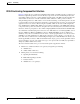
Chapter 2 Provisioning Step by Step Installation and Initial Configuration Starting CEMF Manager Applications. ILOG Views 3.0.2, Copyright (C) 1990-1998 by ILOG. ILOG TGO 1.0.3, Copyright (C) 1997-1998 by ILOG. You initially see the CEMF Logo and Login windows, as shown in Figure 2-9 and Figure 2-10. Figure 2-9 CEMF Logo Window Figure 2-10 CMNM Login Window Note Step 15 The default user name and password values are both admin.
Chapter 2 Provisioning Step by Step Installation and Initial Configuration Upgrading CiscoView CiscoView 5.1 is installed with CMNM. You should check for upgrades and, if any exist, install them. If no CiscoView upgrades exist, you are now ready to install Cisco PTC and its integrated component application, Cisco VRC. Go to the “Installing Cisco PTC 2.1.1 Integrated with Cisco VRC 1.1” section. Step 1 Check the CiscoView web site for the latest supported version of the package: http://www.cisco.
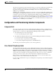
Chapter 2 Provisioning Step by Step Installation and Initial Configuration Table 2-3 Cisco PTC Client Machine Requirements Machine Type Operating System CPU Speed RAM Browser PC Windows2000 or NT 400MHz 256MB Netscape 6.0 (or later) or Microsoft Internet Explorer 5.5 (or later) Sun Ultra60 Solaris 7 or 8 360MHz 256MB Netscape 6.0 (or later) Cisco PTC Dependencies on Platform Versions Table 2-4 describes the devices that are supported by Cisco PTC in the 2.1.
Chapter 2 Provisioning Step by Step Installation and Initial Configuration To obtain access to Cisco VRC documentation, go to the following URL: http://www.cisco.com/univercd/cc/td/doc/product/rtrmgmt/vrc/vrc1_1/index.htm. Optional Product Components The following applications can be launched from the Cisco PTC Topology Manager, however, they are not installed as part of the Cisco PTC installation process.
Chapter 2 Provisioning Step by Step Installation and Initial Configuration Pre Installation Checks This section lists a set of tasks you must perform prior to beginning the Cisco PTC installation process. 1. Make sure the Cisco PTC CNSC CORE and CNS INTEGRATION BUS packages were not previously installed on the Cisco PTC server machine: #pkginfo -l CNSC #pkginfo - l TIBRV The above checks should return error messages when the packages are not found. Tip 2.
Chapter 2 Provisioning Step by Step Installation and Initial Configuration Copying Cisco PTC Files From the Product CD Step 1 Insert the Cisco PTC product CD into the CDROM drive. Step 2 Open a X-terminal window and log in as user root. Step 3 Set the terminal mode to C shell: ptc-tme# csh Step 4 Set the DISPLAY environment variable: ptc-tme# setenv DISPLAY 171.71.73.38:0.
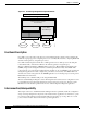
Chapter 2 Provisioning Step by Step Installation and Initial Configuration The Cisco PTC Installation window appears, as shown in Figure 2-11, allowing you to install the following packages: • CNSC - CORE • CNS INTEGRATION BUS • CNS SECURITY • JAVA • TOMCAT • VRC Figure 2-11 Cisco PTC Installation Window Cisco Internet OSS for VoIP: Infrastructure Manager Implementation Guide 2-60 OL-2706-01
Chapter 2 Provisioning Step by Step Installation and Initial Configuration Step 14 Click the CNSC - CORE check box. Only the CNSC - CORE check box should be selected at this time. Note Step 15 If you cannot see the bottom of the Cisco PTC Installation window (the Start and Exit buttons), it is likely that your screen resolution is too low. A minimum of 1280x1024 is required. Enter the following information in the Input Parameters fields: Product Source Directory: /opt/PTC-2.1.
Chapter 2 Provisioning Step by Step Installation and Initial Configuration Before proceeding, you must refer to the “Caveats” section in the Release Notes for Cisco Packet Telephony Center, Release 2.1 to see whether you must modify any of the parameters in the /etc/system file. After the following the instructions in the “Caveats” section: http://www.cisco.com/univercd/cc/td/doc/product/rtrmgmt/ptc/2_1/relnotes/relnote.htm#65500. Assuming compliance, proceed. Step 19 Reboot the Cisco PTC machine.
Chapter 2 Provisioning Step by Step Installation and Initial Configuration VENDOR: TIBCO Software INC. PSTAMP: 99/12/10 INSTDATE: Sep 24 2002 15:54 EMAIL: support@tibco.com STATUS: completely installed FILES: 133 installed pathnames 15 directories 30 executables 2 setuid/setgid executables 23870 blocks used (approx) Step 11 Once again, make sure the package was “completely installed”.
Chapter 2 Provisioning Step by Step Installation and Initial Configuration Step 7 Verify the JAVA package installation was successful by checking whether the /opt/vnm/common/jre directory exists. ptc-tme# cd /opt/vnm/common ptc-tme# ls Step 8 dcdsrvr installer uninstallCnsIB.sh uninstallJava.sh installEnvVar.csh jakarta-tomcat-3.3.1 uninstallCnsSec.sh uninstallSybase.sh installEnvVar.sh jre uninstallGdpm.sh uninstallTomCat.
Chapter 2 Provisioning Step by Step Installation and Initial Configuration Step 4 Verify the VRC package installation was successful by verifying that the following links and directories exist under the /opt/vnm directory: a. a gdpm soft link. b. a mysql soft link. c. the mysql-3.23.42-sun-solaris2.8-sparc (for Solaris 8) directory exists.
Chapter 2 Provisioning Step by Step Installation and Initial Configuration lrwxrwxrwx 1 root other 3.23.51-sun-solaris2.8-sparc vnm 37 Sep 24 16:42 mysql -> mysqlcom- drwxr-xr-x 13 root 512 Jun 13 09:04 mysqlcom-3.23.51-sun-solaris2.8-sparc drwxr-xr-x 4 vnm vnm 512 Sep 24 15:39 packages drwxr-xr-x 2 vnm vnm 512 Sep 27 13:51 rel -rwxr-xr-x 1 vnm vnm 40 Sep 30 17:36 status.txt -rwxr-xr-x 1 vnm vnm 1727 Sep 24 15:41 system.
Chapter 2 Provisioning Step by Step Installation and Initial Configuration Step 4 To confirm the /usr/sbin/share directory is in your PATH variable, execute: ptc-tme# which share /usr/sbin/share Step 5 Go to the Cisco PTC scripts directory: ptc-tme# cd /opt/cisco/vnm/tools/scripts Step 6 Run the configureVNM script: ptc-tme# ./configureVNM The Configure VNM window appears. Step 7 Choose Option number 2 (Install MCG): ----------------VNM Configuration ----------------- Main Menu --------- 1.
Chapter 2 Provisioning Step by Step Installation and Initial Configuration Step 9 Enter the File Transfer Protocol (SFTP or FTP) method to be used: Enter the Transfer Mode (SFTP/FTP): FTP Installing on host cmnm-pri TransferMethod FTP Sharing volume /opt/cisco/vnm via NFS found share -F nfs -o ro -d "VNM CDROM" /opt/cisco/vnm MOUNTPOINT-----/opt Restarting NFS... Done.
Chapter 2 Provisioning Step by Step Installation and Initial Configuration 4> Uninstall VCG Client q> Quit Choose an option: 1 The MCG Server and Client installation process starts. Step 11 Press Enter to choose the default installation location. Step 12 If you entered SFTP in Step 9, you are prompted with the following message: “The authenticity of host cannot be established. Client machine is .
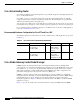
Chapter 2 Provisioning Step by Step Installation and Initial Configuration Cisco PTC Patch Information This section identifies and describes how to install the Cisco PTC 2.1.1 patches you must install after the Cisco PTC product and component software have been installed. Table 2-5 Cisco PTC 2.1.1 Patches Patch Number Patch File Name 1 02_01_18_01.tar 2 02_01_18_02.tar 4 02_01_18_04.tar You can access the Cisco PTC 2.1.1 patches at the following location: http://www.cisco.
Chapter 2 Provisioning Step by Step Installation and Initial Configuration System Startup This section describes how to start the Cisco CNS Security and Cisco CNS Integration Bus processes and then perform a Cisco PTC Cold Start.
Chapter 2 Provisioning Step by Step Installation and Initial Configuration Version 6.4.8 CNS INTEGRATION BUS is up Note Step 5 If the Cisco CNS IE2100 appliance and the Cisco PTC Server machine are in different subnets, you must configure the Cisco CNS Integration Bus and Cisco CNS IE2100 appliance as described in the “Post Installation Configuration” section, prior to performing the following steps.
Chapter 2 Provisioning Step by Step Installation and Initial Configuration Step 10 Edit the LocalStrings.properties file: ptc-tme% vi LocalStrings.properties props.baseurl=http://172.19.49.18:8080/topology/servlet/ props.rmiserverhostname=172.19.49.18 props.codebaseurl=http://172.19.49.18:8080/lib props.provsvrhost=172.19.49.18 props.actualinstallationdir=/opt/vnm props.uploadedfilesdir=/opt/cisco/vnm/topodisc/uploadedfiles props.seedfilelocation=/opt/cisco/vnm/topodisc/seedfile.txt props.
Chapter 2 Provisioning Step by Step Installation and Initial Configuration Step 11 Go to the /opt/cisco/vnm directory: ptc-tme% cd /opt/cisco/vnm Perform a Cisco PTC Cold Start: Note Cisco PTC can be started in either Standalone (the default) or Integrated mode. In Standalone mode, only Cisco PTC Server processes are started. In Integrated mode, Cisco PTC Server and Cisco VRC processes are started. Step 12 Wait until the “Start Operation is Complete” and “Cisco PTC is Up” messages appear.
Chapter 2 Provisioning Implementation and Testing Step 3 Open the java.policy file and replace the contents of the java.policy file with the following lines: // Standard extensions get all permissions by default grant { permission java.security.AllPermission; }; Step 4 Save the modified java.policy file, then exit the text editor. Step 5 Open a web browser of your choice.
Chapter 2 Provisioning Related Documents Cisco Internet OSS for VoIP: Infrastructure Manager Implementation Guide 2-76 OL-2706-01