Kamibot Coding Manual Vol. PC Ver. 1.
Table of Contents 1. KamiBlock Installation 3 2. Kamibot Setup 7 3. In Case of Kamibot Installation Failure 9 4. KamiBlock 4-1. Starting up KamiBlock 13 4-2. Connecting to Kamibot 14 4-3. Kamibot Basic Mode 15 4-4. Kamibot Basic Mode Blocks 16 4-5. MapBoard Mode 19 4-6. MapBoard Mode Blocks 20 4. Changing Color of RGB LEDs 21 5. Rotating the Servo Motor 23 6. Controlling the DC Motors 24 7. Checking The Value Returned by Ultrasound Sensor 26 8.
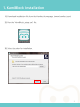
1. KamiBlock Installation 1) Download installation file from the Kamibot homepage. (www.kamibot.com) 2) Run the “KamiBlock_setup.exe” file. 3) Select Location for installation.
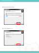
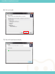
1. KamiBlock Installation (cont.) 4) Select A Start Menu Folder. 5) Create a Desktop Icon.
1. KamiBlock Installation (cont.) 6) Click on Install. 7) Files will install automatically.
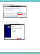
1. KamiBlock Installation (cont.) 8) Install Arduino USB Driver. 9) Click Finish. Installation is Completed.
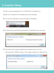
2. Kamibot Setup 1) After connecting Kamibot to PC via USB cable, turn Kamibot on. 2) Wait for a notification for Installing device driver software. 3) Click on the notification to check the status of installation. 4) The device driver will install automatically. This will take a very short time. 5) After device driver has successfully been installed, take note of the USB Serial Port (COM00) number.
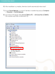
2. Kamibot Setup (cont.) 6) After Installation is complete, Kamibot should automatically reboot itself 7) Access Device Manager to check if Kamibot is installed by going to Computer → Properties → Device Manager. 8) Your device will appear under Ports (COM & LPT) → USB Serial Port (COM00).
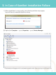
3. In Case of Kamibot Installation Failure 1) When Installation is unsuccessful, the following window may appear. User will have to manually install the drivers. 2) Right-click Computer → go to Properties → go to Device Manager. * The Kamibot will appear with a exclamation mark under Other devices as USB Serial Port.
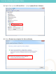
3. In Case of Kamibot Installation Failure 3) Right Click on the USB Serial Port → Select Update Driver Software 4) Select Browse my computer for driver software.
3.
3. In Case of Kamibot Installation Failure 7) Driver has successfully been installed. Close window. 8) If Installation fails, try again from the beginning of this section.
3-1. Starting up KamiBlock 4 5 1 2 3 1 Stage : Area that displays sprites, and backgrounds created by the user. 2 Stage Design: Users can find,decorate, and create backdrops for their stage. 3 Sprite Library: Users can find, decorate, and create sprites for their stage 4 Block Bank: Blocks for controlling the sprites placed on the stage are in this area 5 Workspace: Users can stack and build with blocks from the Block Bank in this area.
3-2. Connecting to Kamibot 1) After connecting Kamibot to PC via USB cable, turn Kamibot on. 2) Select your Kamibot under Connect → COM00 (KamiBot) (The number may differ on different PCs) 3) When successfully connected, Kamibot should automatically reboot itself.
3-3. Kamibot Basic Mode 1) For Basic scripting, go to Boards (Kamibot) → select “Kamibot”. 2) You can move Kamibot with block scripts that you put together in the Workspace.
3-4. Kamibot Basic Mode Blocks 1) Kamibot Program A block used for Arduino Mode. 2) Move Forward Speed Move forward at user defined speed. (Value ranges between 0~255.) 3) Move Left Speed Turn left at user defined speed. (Value ranges between 0~255.) 4) Move Right Speed Turn right at user defined speed. (Value ranges between 0~255.) 5) Move Backward Speed Move backward at user defined speed. (Value ranges between 0~255.
3-4. Kamibot Basic Mode Blocks (cont.) 6) Move Forward Speed Right/Left Move forward with different speeds for Left and Right motor. 7) Move Backward Speed Right/Left Move backward with different speeds for Left and Right motor. 8) Stop Stops all movement.
3-4. Kamibot Basic Mode Blocks (cont.) 9) set RGB LED Color Set RGB LED to user defined color. (Red, Pink, Blue, Sky Blue, Green, Yellow) 10) Servo Servo rotates to user defined degree. (rotation ranges from 0~180 degrees) 11) Ultrasound Sensor Returns value of distance of obstacle infront of sensor. (sensor detects obstacles up to 2~100cm away.) 12) IR (infrared) Sensor 5 IR sensors on the underside of Kamibot differentiate between white and black.
3-5. MapBoard Mode 1) When using Kamibot with the MapBoard, go to Boards (Kamibot) and select →“KamiBot (MapBoard)”. 2) Code Blocks under Robot in the Block Bank will be different than the Blocks in Basic Mode. 3) Place Kamibot on an intersection (where the black lines cross each other).
3-6. MapBoard Mode Blocks These blocks are used with Kamibot and a mapboard together. Kamibot should be place on an intersection on the mapboard at the start. 1) Move Forward Block Moves forwards the number of times defined by user. 2) Turn Left Turns left 90 degrees at intersection. 3) Turn Right Turns right 90 degrees at intersection. 4) Turn Back Turn around 180 degrees at intersection.
4.
4.
5. Rotating the Servo Motor Click Arrow for Drop down menu 1) Turn to 0 degrees 2) Turn to 45 degrees 3) Turn to 90 degrees 4) Turn to 135 degrees 5) Turn to 180 degrees ※ EXAMPLE ※ Turn servo motor left and right repeatedly.
6. Controlling the DC Motors The speed of the DC motors can be defined by the user. Input value can range between 0~255.
6. Controlling the DC Motors ※ EXAMPLE 1※ Try Moving Kamibot around. Blocks used: -When clicked -Move forward speed -Move left speed -Move right speed -Move backward speed -Wait 1 second -Stop ※ EXAMPLE 2※ Try Moving Kamibot around.
7. Checking the Value Returned by Ultrasound Sensor We will make the Kamibot sprite on the stage say the value returned by the ultrasound sensor. ※ EXAMPLE ※ Make Kamibot move forward, and make it move backwards when there is an obstacle 5 centimeters in front of it.
8. Checking the Value Returned by IR (Infrared) Sensor Lets make the Kamibot sprite on the stage say “Black” or “White” depending on the value returned by the IR sensor. If an IR sensor detects the color Black, it will return a value of 1. If it detects White, it will return a value of 0. infrared sensor No. 5 infrared sensor No. 4 infrared sensor No. 3 infrared sensor No. 2 infrared sensor No. 1 Black = 1 White = 0 ※ EXAMPLE ※ Make Kamibot move Forward and stop if it detects black.
9. Navigating the Mapboard Lets try treasure hunting on the mapboard.
9.
10. Arduino Mode In Arduino Mode, users can see code blocks translated to the C++ programming language side-by-side.
10. Arduino Mode In Arduino Mode, users can upload their scripts to Kamibot to reprogram it however they choose. Lets reprogram Kamibot to become a strobe light whenever we turn it on. 1) When UPLOADING, must be the base block. 2) Go to Edit and select → “Arduino mode”.
10. Arduino Mode To revert Kamibot to its programmable state, switch Kamibot on, and make sure Kamibot is plugged into the PC. Make sure Kamibot is connected to the Program 7) Go to Serial Port Connected and select→ “Install KamiBot Firmware”. 8) Wait for the Firmware to upload. Kamibot will reboot when finished.
11. Arduino IDE Users may want to edit code directly in the Arduino IDE and upload directly to the robot.
11. Arduino IDE 2) Go to Edit and select → “Arduino mode”. 3) Arduino IDE will appear.
11. Arduino IDE 4) Select Board under Board → RBL nRF51822(V1.0 16KB) 5) Connect Serial Port via Tools → Port → COM00 in Arduino IDE. (The number may differ on different PCs) Note: COM 00 number should be the same as the serial port you disconnected earlier.