2Wire Gateway User Guide
Notice to Users ©2007 2Wire, Inc. All rights reserved. This manual in whole or in part, may not be reproduced, translated, or reduced to any machinereadable form without prior written approval. 2WIRE PROVIDES NO WARRANTY WITH REGARD TO THIS MANUAL, THE SOFTWARE, OR OTHER INFORMATION CONTAINED HEREIN AND HEREBY EXPRESSLY DISCLAIMS ANY IMPLIED WARRANTIES OF MERCHANTABILITY OR FITNESS FOR ANY PARTICULAR PURPOSE WITH REGARD TO THIS MANUAL, THE SOFTWARE, OR SUCH OTHER INFORMATION, IN NO EVENT SHALL 2WIRE, INC.
Contents Introduction Networking Technology Overview . . . . . . . . . . . . . . . . . . . . . . . . . . . . . . . . . . . . . . . . . . . . . . . . . . . . 1 System Tab Viewing Your System Summary . . . . . . . . . . . . . . . . . . . . . . . . . . . . . . . . . . . . . . . . . . . . . . . . . . . . . . 2 Network at a Glance Panel . . . . . . . . . . . . . . . . . . . . . . . . . . . . . . . . . . . . . . . . . . . . . . . . . . . 3 System Area of the Network at a Glance Panel . . . . . . . . . . . . . . .
Contents Setting up a Private Network . . . . . . . . . . . . . . . . . . . . . . . . . . . . . . . . . . . . . . . . . . . . . . . . 30 Setting Up a Public Routed Subinterface . . . . . . . . . . . . . . . . . . . . . . . . . . . . . . . . . . . . . . . . 32 Setting Up a Public Proxied Subnet . . . . . . . . . . . . . . . . . . . . . . . . . . . . . . . . . . . . . . . . . . . . 33 Selecting a Default DHCP Pool . . . . . . . . . . . . . . . . . . . . . . . . . . . . . . . . . . . . . . . . . . . .
Contents Local Network - Wireless Settings Page . . . . . . . . . . . . . . . . . . . . . . . . . . . . . . . . . . . . . . . . . . . . . . . 78 Customizing Security Settings . . . . . . . . . . . . . . . . . . . . . . . . . . . . . . . . . . . . . . . . . . . . . . . 79 Additional Settings . . . . . . . . . . . . . . . . . . . . . . . . . . . . . . . . . . . . . . . . . . . . . . . . . . . . . . . 79 Local Network - Configuration Page . . . . . . . . . . . . . . . . . . . . . . . . . . . . . . . . . . . .
Introduction The 2Wire gateway allows you to create a network with your computers and peripheral devices. Following are just a few of the benefits derived from using the 2Wire gateway to network your home or office. High performance integrated modem. 2Wire’s technology improves DSL1 performance, especially for homes further away from the local exchange. It also minimizes common interference found when other devices (such as dimmer switches or fluorescent lighting) are in contact with the DSL line.
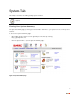
System Tab This chapter describes the 2Wire gateway System features. Note: 2Wire recommends that you use Internet Explorer 5.5 (or higher) or Netscape 6 (or higher). Viewing Your System Summary The System Summary page provides general information and links to your system’s most commonly used features. To access the System Summary page: • Open a Web browser and access the gateway user interface by entering http://gateway.2wire.net. • Click the System tab to open the System Summary page. Figure 1.
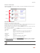
System Tab Network at a Glance Panel The Network at a Glance panel provides a summary of the System, Broadband Link, and Home Network states of your gateway. System Area Broadband Link Area Home Network Area Figure 2. Network at a Glance Panel System Area of the Network at a Glance Panel The System area of the Network at a Glance panel displays your 2Wire gateway model name, the version of gateway software that you are using, and the status of your gateway password.
System Tab Click the Privacy policy link to review the 2Wire privacy policy. Broadband Link Area of the Network at a Glance Panel The Broadband Link area of the Network at a Glance panel displays the overall status of your gateway’s physical connectivity. The diamond symbol in this area indicates the overall status of the broadband link and corresponds to the Internet light on the front of your gateway.
System Tab Accessing the Home Network Summary Page The Home Network Summary page displays information about the devices installed on your network. To access the Home Network Summary page, click the View the home network link. Enabling Enhanced Services 2Wire provides a suite of enhanced services: Web Remote Access, Firewall Monitor, and Parental Controls. If your service provider offers these enhanced services, links to set them up are available on the gateway Home page.
System Tab Setting a System Password Setting a system password protects your gateway settings from being modified or changed by someone who has not been given permission to do so. After setting a system password, you will be required to enter it whenever you attempt to access a gateway configuration page — for example, if you try to change the gateway’s broadband connection settings or upgrade the gateway software.
System Tab 4. Optional: In the Enter Your Hint field, enter a hint. A hint is a word, phrase, or question that reminds you what the password is. There is an I forgot the password link on the password entry page. When you click this link, it shows you your hint and allows you to enter your password. 5. Click SAVE. To disable password protection, deselect the Enable checkbox and click SAVE.
System Tab To obtain access to your system: 1. In the System Key field enter the 10-digit system key located on the bottom of your gateway. 2. In the Enter New Password field, enter a new system password. In the Confirm New Password field, reenter the system password. 3. In the Enter Your Hint field, enter an appropriate hint as described under “Setting a System Password” on page 6. 4. Click Submit.
System Tab Viewing System Details The System Details page provides information about your gateway, any enhanced services you may have, and provides a link that you can use to restart your system. To view the System Details page: • Open a Web browser and access the gateway user interface by entering http://gateway.2wire.net. • Click the System tab. • Click the View details link in the System area of the Network at a Glance panel to open the View System Details page. Figure 6.
Broadband Link Tab This chapter describes the 2Wire gateway Broadband Link features, and provides detailed instructions on how to customize your broadband settings. Viewing Your Broadband Link Summary The Broadband Link Summary page provides general information about the current status of your broadband link connection and your system configuration. To access your Broadband Link Summary: • Open a Web browser and access the gateway user interface by entering http://gateway.2wire.net.
Broadband Link Tab Connection Speed Connection Speed shows the incoming and outgoing data rates of your DSL connection, measured in kilobits per second (Kbps). Incoming is the speed of data flowing from the Internet to your network; Outgoing is the speed of data flowing from your network to the Internet. Connection Information Connection Information shows the following basic system configuration information: • Internet Address.
Broadband Link Tab Connection Details The View connection details link accesses the Broadband Link Details page, which displays technical information about your broadband connection. Technical support representatives use this information to help troubleshoot problems with your broadband connection. Figure 8. View Broadband Link Details Page The following table shows the information that may be displayed on the Broadband Link Details page.
Broadband Link Tab Item Description DSL Connection DSL Line (Wire Pair) The DSL signal can be transmitted on Line 1 (inner pair) or Line 2 (outer pair). During installation, the gateway automatically detects on which line the DSL signal is being transmitted. Protocol Displays which DSL protocol is being used to communicate between your system and your service provider.
Broadband Link Tab Item Description Username The name used to connect with your Internet Service Provider (ISP). Your username was either assigned to you or configured by you during the install process. The correct username is required to successfully connect to the Internet. Internet Address A number that is assigned to a computer so that it can communicate on a network and on the Internet.
Broadband Link Tab Item Description Primary Domain Name Server Part of the Internet address settings. A domain name is a meaningful, easy-to-remember “handle” for an Internet address. The DNS allows Internet users to specify a name (domain name) to reach a Web page (for example, www.domainname.com) instead of its Internet address (for example, 111.222.111.222). When you enter the name of a Web location (URL), the DNS looks up the name and resolves it to the Web page’s Internet address.
Broadband Link Tab Monitor Internet Connection The Monitor Internet connection link launches the Speed Meter. The Speed Meter measures the actual rate at which data is coming into (Incoming Kbps) and going out of (Outgoing Kbps) your system. It measures real-time data throughput in Kilobits per second and displays in one-second intervals. The Speed Meter monitors the actual data rates while connecting to a Web site.
Broadband Link Tab • Click the Diagnostics link under the tab to open the Broadband Link Diagnostics page. Figure 9. Broadband Link Diagnostics Page To update the broadband link status, click REFESH. To initiate a full test of your broadband link, click TEST. The test will take several minutes, during which the system reestablishes all broadband connections. You will not be able to access the Internet until the test is complete.
Broadband Link Tab • Click the Statistics link under the tab to open the View Broadband Link Statistics page. Figure 10. View Broadband Link Statistics Page The Transmit and Receive Data panel displays the following information. • Transmit. The cumulative number of IP packets transmitted, the cumulative number of IP payload bytes transmitted, and the number and percentage transmitted in error. • Receive. The number of bytes and packets received, and the number and percentage received in error.
Broadband Link Tab The Data Errors panel displays the following information. Data Error Description ATM Cell Header Errors The number of ATM cell header CRC errors since the 2Wire gateway was last restarted, and the elapsed time since the last cell header error. ATM Loss of Cell Delineation The number of ATM loss of cell delineation errors since the 2Wire gateway was last restarted, and the elapsed time since the last loss of cell delineation error.
Broadband Link Tab Data Error Description DSL Uncorrected Blocks The number of uncorrected DSL superframes that had data errors detected. ISP Connection Establishment The number of times the ISP connection was established since the statistics were last reset, and the elapsed time since the last establishment. Using Advanced Settings The Advanced Settings page allows you to manually configure your DSL and Internet connection settings.
Broadband Link Tab • Click the Advanced Settings link under the tab to open the Broadband Link Advanced Settings page. Figure 11. Broadband Link Advanced Settings Page Modifying DSL and ATM Settings By default, the gateway automatically detects which DSL line to use. The DSL and ATM panel allows you to select a DSL line and manually configure your ATM settings. 1. From the DSL Line Selection drop-down menu, select Automatic, Line 1 (inner pair), or Line 2 (outer pair). 2.
Broadband Link Tab 3. From the ATM Encapsulation drop-down menu, select Bridged LLC, Bridged VC-Mux, Routed LLC, or Routed VC-Mux. 4. In the ATM/PVC Search field, click the Enabled or Disabled radio button. 5. Click SAVE. Modifying Broadband Connection Settings The Broadband Connection panel allows you to modify your broadband connection. 1. From the Connection Type drop-down menu, select the connection type: PPPoE, PPPoA, Direct IP (DHCP or Static), or Routed IPoA.
Broadband Link Tab Modifying the Broadband IP By default, the gateway automatically obtains its Internet address. The Broadband IP panel allows you to manually configure your Internet address settings. 1. Click the Manually configure IP address settings radio button. 2. In the IP address field, enter the IP address you want the gateway to use. 3. In the Subnet Mask field, enter the subnet mask you want the gateway to use. 4.
Home Network Tab This chapter describes the 2Wire gateway Home Network features, and provides detailed instructions on how to customize your network settings. Viewing Your Home Network Summary The Home Network Summary page displays information about the devices installed on your network. To access the Home Network Summary page: • Open a Web browser and access the 2Wire gateway user interface by entering http://gateway.2wire.net. • Click the Home Network tab to open the View Network Summary page.
Home Network Tab Each device on your home network is represented with a computer icon. If the “show inactive devices” option is enabled, and the device becomes inactive because it is powered off or removed from your network, this icon will display as Inactive. Note: For additional information, refer to “Showing a Device as Inactive” on page 33.
Home Network Tab Depending on the permissions you have set for devices on your network, the following links may display next to the device: • Access shared files. Accesses the shared files available from this computer. This feature only works with Microsoft Windows computers that have shared files and file sharing installed. Note: If your computer is configured with a static IP address, this link will not appear. • Edit firewall settings.
Home Network Tab • Click the Wireless Settings link to open the Configure the Wireless Network page. Figure 13.
Home Network Tab The Current Settings panel shows the 2Wire gateway’s wireless access point settings: • Access Point. The designated name of the wireless access point. • Network Name. The name assigned to your wireless network. The default is 2WIREXXX, where XXX represents the last three digits of your 2Wire gateway serial number (for example, 2WIRE954). • Channel. The radio frequency band the access point uses for your wireless network (the default is 6).
Home Network Tab Configuring MAC Filtering The Media Access Control (MAC) address is a unique number assigned to computer hardware. When setting up your network, you can set your Wireless Broadband Router to give access only to certain MAC addresses. By doing so, you limit access only to your computer hardware and no one else's. 1. In the MAC Filtering pane, click the EDIT MAC FILTERING button. The Wireless MAC Filtering page opens. 2. Click the Enable checkbox. 3.
Home Network Tab • DTIM Period (seconds). Determines at which interval the access point will send its broadcast traffic. The default value is 4 seconds. • Maximum Connection Rate. The maximum rate at which your wireless connection works (1, 2, 5.5, 11, or 22 Mbps for 802.11b-based models; 1, 2, 5.5, 11, 6, 9, 12, 24, 36, 48, or 54 Mbps for 802.11b/ g-based models). • Power Setting. Allows you to select the power level for your wireless connection.
Home Network Tab • Click the Advanced Settings link under the tab to open the Edit Advanced Home Network Settings page. Figure 14.
Home Network Tab 1. Click the radio button that corresponds to the IP address range you wish to use. If you select the 172.16.0.0 / 255.255.0.0 or 10.0.0.0 / 255.255.0.0 range, continue to step 5. If you select Configure manually, continue to step 2. 2. In the Router Address field, enter the IP address used by your system on the private home network. 3. In the Subnet Mask field, enter the subnet mask. The subnet mask is determined by the home network IP address range settings. 4.
Home Network Tab Setting Up a Public Proxied Subnet The Public Proxied Subnet pane allows you to create a local network that has broadband-accessible IP addresses. Public Proxied Subnet is a public network in which the local network is an extension of the broadband network and does not require any special routing. Computers that are assigned Public Proxied Subnet IP addresses operate without Network Address Translation (NAT).
VoIP Network Tab This chapter describes the 2Wire gateway VoIP Network features, and provides detailed instructions on setting up a VoIP network. Configuring the VoIP Phones To configure VoIP via the gateway user interface, follow these steps. 1. Access the gateway user interface by opening a web browser and entering http://gateway.2wire.net. Click the Voice Network tab. The View Voice Network page opens 2. In the Voice Network Setup box, click Introduction. The Introduction page displays.
VoIP Network Tab 3. Click NEXT to continue. The Set Up Phones (Step 1: Phone Wiring) page displays. Follow the on-screen instructions. 4. Click NEXT. The Step 2: Set Up Phone Lines page opens. Activate a line by checking the box next to Phone Number/Userid. Click EDIT to change the settings. 5. The account is based on username or phone number. To change this setting, enter a Username or phone number in the User Name box.
VoIP Network Tab and password in the Auth Username and Auth Password boxes under the Credentials subheading. Click SUBMIT to continue. Next, the Phone Settings page opens. 6. The Phone Settings page allows you to match each telephone to a phone line.To do so, click EDIT.
VoIP Network Tab 7. In the Phone Name field, select a name to associate with the phone. If you have more than one digital voice line, in the Assign Number field select the phone line you wish to associate with this phone. Click SUBMIT to continue. The Phone Settings (Step 3: Match each Phone to a Line) page displays. 8. Check the box next to each phone line to activate it. To identify and locate each phone listed, click RING NOW, which will momentarily ring that telephone.
VoIP Network Tab 9. Congratulations, setup is complete. Click DONE to return to the Voice Network summary page. If you want to change your settings, go to the System Summary page, then click the Voice Network tab. Note: To make any broadband connection settings changes, such as configuring the voice servers, refer to the Management and Diagnostic Console. See “Management and Diagnostic Console” on page 58.
Firewall Tab This chapter describes the 2Wire gateway firewall features, and provides detailed instructions on how to modify the firewall settings. Firewall Features The 2Wire gateway has a professional-grade firewall to help prevent unauthorized users from accessing your local network. The 2Wire gateway firewall includes the following features: Stateful packet inspection. Blocks common Denial of Service attacks (such as SYN/FIN flooding or Smurf), and detects and logs TCP and UDP port scans.
Firewall Tab Viewing Your Firewall Summary The Firewall Summary page provides summary information and links to the most commonly used securityrelated features of your system. To access the Firewall Summary page: • Open a Web browser and access the gateway user interface by entering http://gateway.2wire.net. • Click the Firewall tab to open the View Firewall Summary page. Figure 15. View Firewall Summary Page The Firewall Settings panel displays the Current Settings for your firewall. • Default.
Firewall Tab Click VIEW DETAILS to access the Firewall Details page, which shows a list of all the devices that have applications configured in the firewall and the details of these configurations. Figure 16. View Firewall Details Page If you have the Firewall Monitor enhanced service, the Firewall Monitor panel shows a brief summary of the number of attacks that were blocked for the current day and week. Click VIEW DETAILS to access the Monitor the Firewall page.
Firewall Tab • Click the Firewall Settings link under the tab to open the Edit Firewall Settings page. Figure 17. Edit Firewall Settings Page 1. From the Select a computer pull-down menu, select the computer that you wish to host the application. 2. Click the Allow individual application(s) radio button. 3. In the Applications panel, select an application. 4. Click the ADD > button. The application you selected now appears in the Hosted Applications pane. 5. Click DONE.
Firewall Tab To stop hosting an application: 1. In the Hosted Applications panel, select the application you wish to stop hosting. 2. Click the < REMOVE button. 3. Click DONE. Updating the Application Profile List If the application you want to host does not appear in the Application Profile list, you may need to update the application list. If an update is available, the UPDATE APPLICATION LIST button appears above the list of application profiles.
Firewall Tab • In the Applications panel, click the Add a new user-defined application link to open the Edit Application page. Figure 18.
Firewall Tab 1. In the Application Name field, enter a name for the application profile. You can enter any name you like, although it’s recommended that you use the name of the application (for example, Redwing Game Server). 2. In the Definition panel, create a definition for your application. A definition consists of a series of protocol-specific ports that are to be allowed through the firewall.
Firewall Tab • In the Applications panel, click the Edit or delete user-defined application link. The Select a Hosted Application page opens. Figure 19. Select a Hosted Application Page 1. In the User-Defined Application Profiles panel, highlight the application you wish to edit or delete. f. To edit the application profile, click EDIT. The Edit Application screen appears. Make the necessary changes to the application profile and click DONE. g. To delete the application profile, click DELETE.
Firewall Tab Because all filtered traffic is forwarded to the designated computer, you should use DMZplus mode with caution. A computer in DMZplus mode is less secure because all available ports are open and all incoming Internet traffic is directed to this computer. To configure DMZplus: • Open a Web browser and access the 2Wire gateway user interface by entering http://gateway.2wire.net. • Click the Firewall tab.
Firewall Tab 3. Click DONE. 4. Access the computer that you selected in step 1. 5. Confirm that the computer is configured for DHCP. If it is not, configure it for DHCP. 6. Restart the computer. When the computer restarts, it receives a special IP address from the system and all unassigned TCP and UDP ports are forwarded to it. To stop DMZplus: 1. From the Select a computer pull-down menu, select the computer for which you would like to disable DMZplus. 2.
Firewall Tab • Click the Firewall Log link under the tab to open the View Firewall Log page. Figure 21. View Firewall Log Page The following table provides additional information about the log entries. Severity Details • Info. Informational only—the event does not imply a threat to network security. • Low. Occurs when the firewall detects a low-level threat to the network, such as an invalid IP header or invalid packet length. • Medium.
Firewall Tab Configuring the Firewall (Advanced) The Edit Advanced Firewall Settings page allows you to configure advanced features on your firewall. Figure 22. Edit Advanced Firewall Settings Page Note: These features should be used only if you are thoroughly familiar with firewalls and networking.
Firewall Tab Enabling Advanced Security Your 2Wire gateway firewall already provides a high level of security. You can configure the firewall to provide advanced security features, including stealth mode, strict UDP, or block pings. Stealth Mode In normal firewall operation, when an unknown remote device makes a request to connect to a user’s network the firewall does not allow the connection to be made and responds with a “connection not available” message.
Firewall Tab • Click the Advanced Settings link under the tab to open the Edit Advanced Firewall Settings page. 1. In the Security pane, click the Stealth Mode checkbox. 2. Click SAVE.
Firewall Tab Block Ping Ping is a basic Internet program that, when used without malicious intent, allows a user to verify that a particular IP address exists and can accept requests. Ping is used diagnostically to ensure that a host computer you are trying to reach is operating. It can also be used to see how long it takes to get a response back from a specific host computer.
Firewall Tab Strict UDP Session Control Enabling this feature provides increased security by preventing the 2Wire gateway from accepting packets sent from an unknown source over an existing connection. Strict UDP instructs the 2Wire gateway to be more restrictive about what packets are allowed to transmit over an established connection from a local network computer to the Internet.
Firewall Tab Allowing Inbound and Outbound Traffic The Inbound and Outbound Control pane displays some common protocol types. When one of the Inbound protocol boxes is checked, the firewall allows the corresponding protocol to pass through from the Internet to the network. If one of the Outbound protocol boxes is checked, the firewall allows the traffic from the network to pass through the firewall to the Internet.
Firewall Tab The following table lists the attacks for which the gateway firewall filters continuously check. Attack Description and Action Taken Excessive Session Detection When enabled, the firewall will detect applications on the local network that are creating excessive sessions out to the Internet. This activity is likely due to a virus or “worm” infected computer (for example, Blaster Worm). When the event is detected, the gateway displays a HURL warning page.
Firewall Tab • Click the Advanced Settings link under the tab to open the Edit Advanced Firewall Settings page. Figure 23. Edit Advanced Firewall Settings Page 1. In the Attack Detection panel, deselect the appropriate checkbox. 2. Click SAVE.
Management and Diagnostic Console This chapter describes the 2Wire gateway Management and Diagnostic Console (MDC). The Management and Diagnostic Console provides information about the status of the 2Wire gateway, its broadband network connections, attached home networking devices, system and security information, and a running log of any error conditions. You can use the tools provided to: • View configuration and service provisioning information. • View operation logs. • Perform diagnostic tests.
Management and Diagnostic Console Group Link Local Network Device List Wireless Configure Firewall Settings Detailed Information Advanced Settings Voice Summary Configure Server Configure Line Association Troubleshooting DSL Diagnostics Event Log Network Tests Upgrade History Resets Advanced Syslog Settings Provisioning Info Configure Time Services Configure Services Static Routes DNS Resolve Traffic Shaping Link Manager Detailed Log Note: The link groups that display are dependent on the 2Wire g
Management and Diagnostic Console System Summary Page The System Summary page shows general information about the 2Wire gateway, its configuration, and components. For example, it shows the hardware and software version being used by the 2Wire gateway. Broadband Link Pages The Broadband Link pages show summary, detailed status, and statistical information about the 2Wire gateway broadband link; and lets you change configuration settings.
Management and Diagnostic Console Remote Management Feature Management and Diagnostic Console pages that affect gateway configuration can be accessed remotely only if your organization has enabled the Remote Management feature. If the feature is not enabled, an error message will display when you click the link to access the following pages.
Management and Diagnostic Console System Summary Page The System Summary page shows general information about the 2Wire gateway, its configuration, and components. Figure 24. MDC System Summary Page Depending on the service provider and the components installed, the System Summary page includes the following information: Item Description System Model 2Wire gateway model number (for example, “2700HGV Gateway”). Serial Number 2Wire gateway serial number. MAC Address 2Wire gateway MAC address.
Management and Diagnostic Console Item Description Hardware Version 2Wire gateway hardware version. Hardware Options The type of peripheral device installed. DSL Modem Type ADSL or ISDN. Current Software 2Wire gateway software version. Configuration Key Code The key code associated with the current provisioning settings. The value is Unprovisioned if the 2Wire gateway has not yet been provisioned.
Management and Diagnostic Console Broadband Link - Summary Page The Broadband Link - Summary page allows you to view 2Wire gateway broadband connectivity-related settings, and reset the Broadband Link and ISP Connection. Figure 25. MDC Broadband Link Summary Page The Broadband Link – Summary page includes the following information: Item Description Connection Information Broadband Connection Built-in ADSL Modem or External Broadband Modem via Ethernet.
Management and Diagnostic Console Item Description Current Status The current operating condition of the broadband link. Fully operational. The broadband link is operational (including connection to ISP and other services). Initializing. The broadband link is preparing to connect. Establishing link. The broadband link is connecting. No physical link signal. No physical signal detected on the broadband link. Physical connection. The broadband link is connected. Error. There is a broadband link error.
Management and Diagnostic Console Item Description Primary DNS The IP address of the primary DNS server that the 2Wire gateway is to use for DNS name resolution on the broadband link. Secondary DNS The IP address of the secondary DNS server that the 2Wire gateway is to use for DNS name resolution on the broadband link. Host Name The 2Wire gateway host name. This field is only present if the user configures the 2Wire gateway with a host name.
Management and Diagnostic Console Broadband Link - Statistics Page The Broadband Link - Statistics page shows statistics associated with the 2Wire gateway broadband link. Note: To update the information displayed on this page, click the browser’s Refresh button. Figure 26. MDC Broadband Link Statistics Page The Broadband Link – Statistics page includes the following information: Item Description DSL (for DSL models only) Current Rate The DSL downstream and upstream rate, in kilobits.
Management and Diagnostic Console Item Description Current Connection Current Noise Margin. The current downstream and upstream noise margin in dB. Current Attenuation. The current downstream and upstream DSL attenuation in dB. Current Output Power. The current downstream and upstream DSL transmit and receive power in dB. ATM Transmit The cumulative number of cells transmitted, and the number and percentage transmitted in error.
Management and Diagnostic Console Broadband Link - Detailed DSL Statistics Page Note: This link is present only if the 2Wire gateway connects to the Internet via ADSL. The Broadband Link – Detailed DSL Statistics page shows a set of cumulative DSL statistics associated with the 2Wire gateway. Figure 27. MDC Broadband Link Detailed DSL Statistics Page Note: To update the information displayed on this page, click the browser’s Refresh button.
Management and Diagnostic Console The Broadband Link – Detailed DSL Statistics page includes the following information: Item Description ATM Cell Header Errors The number of ATM cell header CRC errors since the 2Wire gateway was last restarted, and the elapsed time since the last cell header error. Loss of Cell Delineation The number of ATM loss of cell delineation errors since the 2Wire gateway was last restarted, and the elapsed time since the last loss of cell delineation error.
Management and Diagnostic Console Item Description Cumulative Sec.w/Severe Errors The number of severely errored seconds since the 2Wire gateway was last restarted, and the elapsed time since the last severely errored second. Corrected Blocks The number of corrected DSL superframes that had data errors detected during reception. Uncorrectable Blocks The number of uncorrected DSL superframes that had data errors detected.
Management and Diagnostic Console Broadband Link - Configuration Page The Broadband Link – Configuration page allows you to modify specific broadband connection settings. Figure 28. MDC Broadband Link Configuration Page Note: Modifying the settings on this page can impact the ability of computers on the local network to access the broadband connection. You should modify these settings ONLY if you are thoroughly familiar with networking.
Management and Diagnostic Console Modifying DSL and ATM Settings By default, the gateway automatically detects which DSL line to use. The DSL and ATM Settings pane allows you to select a DSL line and manually configure your ATM settings. To modify DSL or ATM settings: 1. From the DSL Line Selection pull-down, select Automatic, Line 1(inner pair), or Line 2 (outer pair). 2. In the ATM Circuit Identifier VPI and VCI fields, enter the VPI and VCI you want the gateway to use to connect to the ISP. 3.
Management and Diagnostic Console Modifying Hardware Address By default, the 2Wire gateway uses its built-in hardware address. The Internet Connection Settings Hardware Address Override pane allows you to manually override the MAC address of the broadband connection, which is sometimes required for cable modems that perform MAC address authentication. To modify the hardware address: 1. Click the Override the built-in hardware address radio button. 2.
Management and Diagnostic Console Local Network - Status Page The Local Network – Status page shows the status of the local network. Figure 29. MDC Local Network Status Page The Local Network – Status page includes the following information: Item Description IP Gateway The IP address allocated to the 2Wire gateway. IP Network The IP address used by the network. Subnet Mask The subnet mask allocated to the 2Wire gateway.
Management and Diagnostic Console Item Description DHCP Timeout The time, in minutes, before the DHCP lease must be renewed. Devices Ethernet The number of Active and Inactive Ethernet devices on the network. Wireless (802.11) The number of Active and Inactive wireless devices on the network. USB Specifies whether a USB device is present (Active) on the network. If a USB device is not present, the value is Inactive. Public Network Router Address Defines a separate network on the home side.
Management and Diagnostic Console Local Network - Statistics Page The Local Network – Statistics page shows information about the interfaces on the local network. Figure 30. MDC Local Network Statistics Page The Local Network – Statistics page includes the following information: Item Description Ethernet Transmit The cumulative number of frames transmitted over the Ethernet home network interface, the number of payload bytes transmitted, and the number and percentage of transmitted packets in error.
Management and Diagnostic Console Item Description Receive The cumulative number of frames received over the Ethernet home network interface, the number of payload bytes received, and the number and percentage of received packets in error.
Management and Diagnostic Console Local Network - Device List Page The Local Network - Device List page displays information about each device in the local network. Figure 31. MDC Local Network Device List Page The following information is displayed. • Identity. The name of the device. If the device does not have a name associated with it, the device IP address is displayed. • Type. The type of connection used by the device to connect to the local network: Ethernet, USB, or Wireless. • MAC Address.
Management and Diagnostic Console Local Network - Wireless Settings Page The Local Network - Wireless Settings page allows you to view or change the wireless settings with which your gateway is configured. Figure 32. MDC Local Network Wireless Settings Page The Current Settings panel shows the 2Wire gateway’s wireless access point settings. • Access Point. The designated name of the wireless access point. • Network Name. The name assigned to your wireless network.
Management and Diagnostic Console The Settings panel allows you to change the Network Name and Wireless Channel, and enable SSID broadcast. Customizing Security Settings You should always enable encryption for wireless communication. When encryption is enabled, you must define an encryption key for the 2Wire gateway’s wireless access point and configure that same key on each wireless client that will use your 2Wire gateway wireless network.
Management and Diagnostic Console Local Network - Configuration Page Note: To access this page, your organization must have the Remote Management feature enabled. If the feature is not enabled, an error message will display when you click the link to access this page. The Local Network - Configuration page allows you to change the gateway’s default local network settings. You must click the Submit button for changes to take effect. Figure 33.
Management and Diagnostic Console Note: If you change the local network IP address range, you must renew the DHCP lease on all devices on the gateway’s local network and manually reconfigure all devices configured with static IP addresses. Public Routed Subinterface Settings The Public Routed Subinterface pane allows you to create a local network that has broadband networkaccessible IP addresses by creating a route from the Internet to the public network specified.
Management and Diagnostic Console Firewall - Settings Page Note: To access this page, your organization must have the Remote Management feature enabled. If the feature is not enabled, an error message will display when you click the link to access this page. The Firewall - Settings page allows you to configure the firewall to pass through specific application data to a selected computer. Figure 35.
Management and Diagnostic Console Hosting an Application To host an application on the gateway’s network for Internet users to access (such as a Web server), the firewall must be configured to allow users on the Internet to access it. To host an application: 1. From 1 Select a computer, select a computer from the pull-down menu. 2. From 2 Edit firewall settings for this computer, click the Allow individual application(s) radio button. 3. From the Applications list, select an application profile. 4.
Management and Diagnostic Console To create an application profile: 1. Click the Add a new user-defined application link. The Edit Application page opens. Figure 36. MDC Firewall Edit Application Page 2. In the Application Name field, enter a name for the application profile. 3. In the Protocol field, click the TCP or UDP radio button. If both protocols are required, you must create a definition for each. 4. In the Port (or Range) field, enter the port or port range used by the application. 5.
Management and Diagnostic Console Allowing all applications DMZplus is used for hosting applications if an application will not operate properly using the “Allow individual application(s)” option. When in DMZplus mode, the designated computer: • Shares the gateway’s IP address. • Appears as if it is directly connected to the Internet. • Has all of the unassigned TCP and UDP ports opened and pointed to it. • Can receive unsolicited network traffic from the Internet.
Management and Diagnostic Console Firewall - Detailed Information Page Note: To access this page, your organization must have the Remote Management feature enabled. If the feature is not enabled, an error message will display when you click the link to access this page. The Firewall - Detailed Information page shows detailed information about the gateway’s firewall. Figure 37.
Management and Diagnostic Console Firewall - Advanced Settings Page Note: To access this page, your organization must have the Remote Management feature enabled. If the feature is not enabled, an error message will display when you click the link to access this page. The Firewall - Advanced Settings page allows you to configure the gateway’s firewall. Figure 38.
Management and Diagnostic Console Enabling Security Features The Security pane allows you to configure the gateway’s firewall to provide additional security features. Following are descriptions of the features. Stealth Mode. Enabling Stealth Mode suppresses error responses (for example, TCP resets). Block Ping. Enabling Block Ping blocks ping responses. Strict UDP Session Control. Enabling Strict UDP Session Control prevents another source from “piggybacking” onto a UDP session.
Management and Diagnostic Console Voice Server - Summary Page Note: This link is present only if the 2Wire gateway is VoIP-enabled. The Voice Server - Summary page shows summary information about the voice line(s) and their profile mappings.
Management and Diagnostic Console Voice - Configure Server Page Note: This link is present only if the 2Wire gateway is VoIP-enabled. The Voice - Configure Server page allows you to edit a profile that is associated with your VoIP services, and is used primarily for test purposes. Figure 39.
Management and Diagnostic Console The Edit VoIP Settings panel displays the current SIP settings, and allows you to edit the settings. The following table describes the fields. Server IP Address Corresponds to the SIP proxy address. Port Corresponds to the SIP proxy destination port. Number of Lines Displays the number of lines allowed on the gateway. End Point Domain Displays the IP domain of the SIP endpoint.
Management and Diagnostic Console 5. From the left navigation field under the Voice subheading, click Configure Line Association. The Voice Associate Server page opens. 6. Choose a line and associate it with a server from the pull-down menu. If applicable, repeat the process with another VoIP line. Click SUBMIT.
Management and Diagnostic Console 7. The Voice Server - Summary page displays. Active profiles are listed, as are Line/Profile associations. To make any changes, return to the previous step.
Management and Diagnostic Console Troubleshooting - DSL Diagnostics Page The Troubleshooting - DSL Diagnostics page displays data associated with the 2Wire gateway’s DSL link. Figure 40.
Management and Diagnostic Console Analyzing General Information The General Information pane shows diagnostic information for the current DSL connection (or connection attempt). These values are also listed in the last row of the Training History pane. Item Description Value Comment DSLAM Lists information about the DSLAM, including country, DSLAM vendor, and specifics. DSL Line During line search, the value will alternate between 1 and 2.
Management and Diagnostic Console Item Description Value Comment Impulse Noise Comp. Tones Indicates the number of compensation tones on which impulse noise is detected. For non-interleaved lines with impulse noise, the connect rate will be lowered to avoid excessive errors on the line; however, impulse noise may vary with time, so connect rates may vary accordingly. Impulse Noise Compensation is currently disabled for interleaved lines. The ideal value is zero (0).
Management and Diagnostic Console Item Description Max 2 Latest estimate of maximum achievable rate adjusted for changing line conditions. Max 3 Current or final estimated maximum achievable rate without impulse noise compensation. Mgn 1 Noise margin (in dB) at the start of the connection. Mgn 2 Latest noise margin adjusted for changing line conditions since the connection was first established. Attn Measured attenuation (in dB) of the line. Pwr Transmit power (in dB).
Management and Diagnostic Console Item Description Exit Code Indicates the reason for a lost connection or a terminated training attempt. Following are examples of the typical values that can be represented: ERR_LOF_LIMIT - Retrained due to loss of framing. ERR_LOS_LIMIT - Retrained due to loss of signal. ERR_HI_BER_LIMIT - Retrained due to excessive CRCs. RESTART - System deliberately restarted modem (line search, reprovisioning, or 30second timeout when waiting for DSL signal.
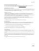
Management and Diagnostic Console Troubleshooting - Event Log Page The Troubleshooting – Event Log page displays all security related events for the broadband and local network. Log information is stored in an 8 KB buffer. When the buffer is full, the oldest items are purged from the log. You can also clear the log contents by clicking the Clear Log button. Figure 41.
Management and Diagnostic Console • HURL. Shows the Broadband Redirect messages that have been enabled by a service provider. • Modem. Shows the current modem log, which registers all significant modem-related events. • System. Shows the current system log, which registers all significant events within the 2Wire gateway since it was last restarted. • WRA. Shows the current Web Remote Access log, which registers all significant Web Remote Accessrelated events.
Management and Diagnostic Console Troubleshooting - Network Tests Page The Troubleshooting – Network Tests page provides the Ping, Traceroute, and DNS Query tools, which help diagnose problems with the 2Wire gateway or 2Wire gateway connections. Figure 42. MDC Troubleshooting Network Tests Page The Ping test allows you to ensure that the 2Wire gateway can send data packets to (ping) a remote host.
Management and Diagnostic Console To perform a ping or traceroute test: 1. From the drop-down menu, select Ping or Traceroute. 2. In the Host field, enter the URL of the host location to which you wish the 2Wire gateway to send the ping or traceroute. 3. In the Test field, enter the number of times you want the ping to occur (the maximum is 25) or the number of hops you want traceroute to trace. 4. In the Packet Size field, enter the packet size you wish to send. The maximum packet size is 576. 5.
Management and Diagnostic Console Troubleshooting - Upgrade History Page The Troubleshooting - Upgrade History page shows a log of all system software upgrades, and lists the upgrades in the order in which they occurred. Figure 43. MDC Troubleshooting Upgrade History Page The Upgrade History page shows the following information. Item Description Model number The 2Wire gateway model number. Hardware version The current 2Wire gateway hardware version.
Management and Diagnostic Console Troubleshooting - Resets Page Note: To access this page, your organization must have the Remote Management feature enabled. If the feature is not enabled, an error message will display when you click the link to access this page. The Troubleshooting – Resets page allows you to reset various components associated with the 2Wire gateway network. Figure 44.
Management and Diagnostic Console The Reset button in the Broadband Link field allows you to reset the 2Wire gateway broadband link. For 2Wire gateway models with a DSL connection, this means the DSL connection is reset. The Reset button in the Gateway field allows you to restart the 2Wire gateway. During 2Wire gateway restart, the Troubleshooting page cannot be accessed until the 2Wire gateway completely restarts and the connection is reestablished.
Management and Diagnostic Console Advanced - Syslog Settings Page The Advanced - Syslog Settings page allows users to maintain a history of security events greater than the capacity of the 2Wire gateway by enabling a syslog server. Note: Use of this feature requires a UNIX or Linux computer running a syslog daemon. Figure 45. MDC Advanced Syslog Settings Page To enable syslog and specify the location of a syslog server: 1. Check the Enable Syslog checkbox. 2.
Management and Diagnostic Console Advanced - Provisioning Info Page The Advanced – Provisioning Info page displays the parameters with which the 2Wire gateway was provisioned. Figure 46.
Management and Diagnostic Console The gateway provisioning parameters are dynamic, and vary depending on the software version that the gateway is running. • Module Configuration. Configuration parameters for modules listed in the Advanced Link Manager States page. The parameters are set by broadband provisioning. • UI Param Configuration. Configuration parameters that affect the user interface and user interaction. The parameters are set by broadband provisioning. • Server Set Configuration.
Management and Diagnostic Console Advanced - Configure Time Services Page Note: To access this page, your organization must have the Remote Management feature enabled. If the feature is not enabled, an error message will display when you click the link to access this page. The Advanced – Configure Time Services page allows you to view and change system time and date settings. Figure 47.
Management and Diagnostic Console To manually set the time and date: 1. Check the Enable checkbox. 2. In the Time field, enter the time in 24-hour HH:MM:SS format (for example, 10:02:11). 3. In the Date field, enter the date in YYYY/MM/DD format (for example, 2006/10/09). 4. From the Time Zone pull-down menu, select the time zone. The available time zones are Hawaii, Alaska, Pacific, Mountain, Arizona, Central, Eastern, Indiana, and Atlantic (Canada). 5.
Management and Diagnostic Console Advanced - Configure Services Page Note: To access this page, your organization must have the Remote Management feature enabled. If the feature is not enabled, an error message will display when you click the link to access this page.
Management and Diagnostic Console IMPORTANT: Bridged mode is intended for testing purposes only, as in WT-062 (ADSL), BER (Bit Rate Error), or industry standard performance tests. When routed mode is disabled, the 2Wire gateway can no longer be managed via CMS, and any DSL connection will require an external PPP connection (via software of third-party hardware). It is strongly recommended that you disable routed mode ONLY if you thoroughly understand the ramifications of doing so.
Management and Diagnostic Console c. Click Internet Protocol (TCP/IP), then click the Properties button. d. In the General tab, click the Use the following IP address radio button. In the IP address field, enter an IP address between 172.16.1.1 to 172.16.1.32. In the Subnet mask field, enter 255.255.0.0. In the Default gateway and Preferred DNS server fields, enter 172.16.0.1. e. Click OK.
Management and Diagnostic Console f. If required, reboot the system for the changes to take effect. 2. Attach the computer to the Local Network port of the 2Wire gateway. 3. In the Web browser address bar, enter 172.16.0.1/management. 4. Click Configure Services. 5. Click the Enable Routing checkbox. 6. Click the Submit Settings button. The gateway PPP, routing, and TCP/IP functions are now re-enabled, and the Local Network LED will turn Green.
Management and Diagnostic Console To change the gateway’s upstream MTU: 1. In the Force Upstream MTU field, enter the value specified by the service provider. 2. Click the Submit button.
Management and Diagnostic Console Advanced - Static Routes Note: To access this page, your organization must have the Remote Management feature enabled. If the feature is not enabled, an error message will display when you click the link to access this page. The Advanced - Static Routes page allows you to manually configure static routes that specify the transmission path data must follow between devices on the gateway network. Figure 49. MDC Advanced Static Routes Page To define a static route: 1.
Management and Diagnostic Console The Route List shows a list of static routes defined by the user.
Management and Diagnostic Console Advanced - DNS Resolve Page Note: To access this page, your organization must have the Remote Management feature enabled. If the feature is not enabled, an error message will display when you click the link to access this page. The Advanced - DNS Resolve page allows users to name network devices (such as printers or Web servers) so that they may be easily accessed by other users on the network. Figure 50.
Management and Diagnostic Console Advanced - Traffic Shaping Page Note: To access this page, your organization must have the Remote Management feature enabled. If the feature is not enabled, an error message will display when you click the link to access this page. The Advanced - Traffic Shaping page allows users to change the 2Wire gateway’s maximum upstream connection rate. Figure 51.
Management and Diagnostic Console Advanced - Link Manager States Page The Advanced – Link Manager States page is a tree representation of the 2Wire gateway interface stack, and shows the internal state of the 2Wire gateway. Figure 52. MDC Advanced Link Manager States Page The Link Manager States page is used to gather dynamic information on internal networking modules, and is based on the runtime configuration of the 2Wire gateway. The information cannot be used to configure the 2Wire gateway.
Management and Diagnostic Console To view information about each node, click the node link. Information displays below the Link Manager States tree, and includes the following: Node Information Description Link status Up. The link is functioning properly. Climbing. The link is attempting to establish a connection. Down. The link is not yet configured. Error. An error has occurred. State changes The number of times the state of the link has changed (since last reboot).
Management and Diagnostic Console The following table shows the possible nodes that can display on the Link Manager States page. Node Description root0 Root for configuration tree. global0 Branch for all global configuration modules. device0 Maintains the status and configuration for devices on the 2Wire gateway. rnat0 Maintains the application mappings and pinholes for nodes on the 2Wire gateway. route0 Maintains all static routes on the 2Wire gateway.
Management and Diagnostic Console Advanced - Detailed Log Page The Advanced – Detailed Log page is a debug log facility modeled after syslog, and provides advanced diagnostic capabilities. Figure 53. MDC Advanced Detailed Log Page Note: The Detailed Log retains a persistent (across upgrades and system restarts) record of gateway events.
Management and Diagnostic Console From the Filter pull-down menus, you can select the level of filtering you want to view (for example, DBG or higher) and the specific gateway component that was affected. Each log displays the following information: • Status level: DBG (debug), INF (informational), NTC (notice), WRN (warning), ERR (error), FTL (fatal), ALR (alarm), or EMR (emergency). • Timestamp (in days, hours, minutes, and seconds) since the state occurred.
Management and Diagnostic Console Filter Description dhcpd DHCP server dsl DSL modem and DSL control module dslice DSL hardware eth Ethernet device ethatm Ethernet to ATM bridge (1483) fw Firewall gpio GPIO (general purpose input/output) device hostapd Wireless access point daemon hpna HPNA interface httpd HTTP daemon initd Initd daemon logs for application control ipsess IP firewall session jtag JTAG device kacct Kernel accounting kelog Kernel event log module kmem Memory
Management and Diagnostic Console Filter Description netdev Network device core nodesd Network device status daemon pdump Packet dump (used for debugging) pkg Package management pki Public Key Infrastructure subsystem ppp Point-to-Point Protocol daemon reset Reset switch driver rpcd RPCD daemon logs for CMS interaction rtatm Routed ATM driver scc Voice SLIC drivers sip SIP sntpc Network time client stream Stream network core syslog Syslog daemon system System level ulib Con
Glossary A Access Point. A device that transports data between a wireless network and a wired network. With the help of the system, a wireless base station is an example of an access point that acts between a wireless node and with other wired PCs and peripherals. D Default Gateway. A device that is placed between network segments (or “subnets”) to ensure that traffic is properly routed between different subnets.
Glossary IP Address. A numeric identifier for your computer. Just as the post office delivers mail to your home address, servers know to deliver data to your computer based on your IP address. IP addresses can be dynamic, meaning that your computer “borrows” the IP address for the necessary timeframe, or they can be fixed, meaning that the number is permanently assigned to your computer. L LAN (Local Area Network).
Glossary PPPoA (Point-to-Point Protocol over ATM). A specification for connecting multiple computer users on an Ethernet LAN to a remote site through common customer premises equipment (such as a modem). PPPoA combines the Point-to-Point Protocol (PPP), commonly used in dialup connections, with the ATM (Asynchronous Transfer Mode) protocol, which supports multiple users in a LAN. PPPoE (Point-to-Point Protocol over Ethernet).
Glossary SYN Flood. A method that the user of a hostile client program can use to conduct a denial-of-service (DOS) attack on a computer server. The hostile client repeatedly sends SYN (synchronization) packets to every port on the server, using fake IP addresses. T TCP/IP (Transmission Control Protocol/Internet Protocol). A method of packet-switched data transmission used on the Internet.
Glossary Channel Range Channel 3 2409.5 MHz - 2434.5 MHz Channel 4 2414.5 MHz - 2439.5 MHz Channel 5 2419.5 MHz - 2444.5 MHz Channel 6 2424.5 MHz - 2449.5 MHz Channel 7 2429.5 MHz - 2454.5 MHz Channel 8 2434.5 MHz - 2459.5 MHz Channel 9 2439.5 MHz - 2464.5 MHz Channel 10 2444.5 MHz - 2469.5 MHz Channel 11 2449.5 MHz - 2474.5 MHz Channel 12 2454.5 MHz - 2479.5 MHz Channel 13 2459.5 MHz - 2484.
Regulatory Information Declaration of Conformity Trade Name: Responsible Party: Address: 2Wire 2Wire, Inc. 1704 Automation Parkway San Jose, CA This device complies with Part 15 of the FCC rules. Operation is subject to the following two conditions: (1) This device may not cause harmful interference, and (2) this device must accept any interference received, including interference that may cause undesired operation.