
Manual

Description
2.1
14
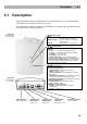
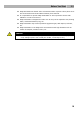
2.1 Description
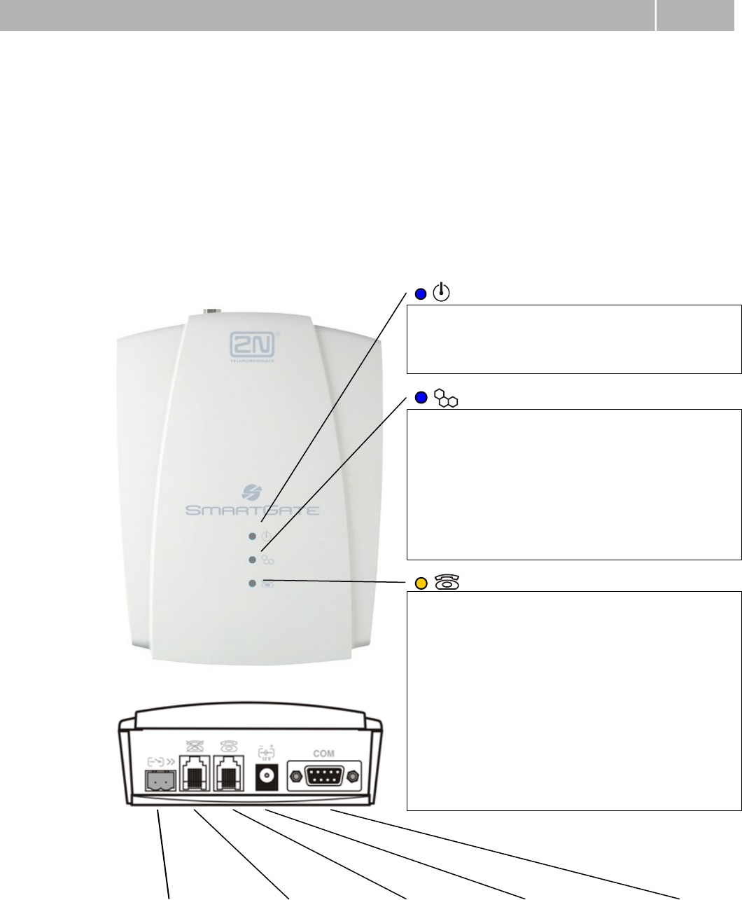
consites of GSM gateway in white plastic cover, removable antenna
and cables for connecting to phone set and PC
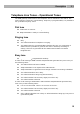
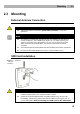
2N
SmartGateindicated by LED diodes on its front side. All possible states
are described in the following figure.
SMS connector
SMS sending input
Telephone line
FXS interface
(RJ 12, 6/2)
Telephone line
FXS interface
(RJ 12, 6/2)
Power supply
connector
(DC Jack 2.1 mm)
RS-232C serial line
(D-Sub 9 pins)
Power supply
Light blue
Power supply is connected and
SmartGate is powered
Flashes 1x in 2 s
HW error, HW error, contact the
manufacturer
No light
Power supply is not connected
GSM network
Light blue
Registered to GSM
Flashes:
1× in 1 s - not registered, SIM card inserted
1× in 3 s - not registered, SIM card not inserted
4× quickly - enter your PIN
8× quickly - enter your PUK
quickly continuously = all functions are blocked.
Phone line programming mode - the LED indicates
signal strength. It flashes repeatedly 1-5 times,
depending on signal strength
Telephone line
No light
Standby
Orange for FXS interface:
Flashes quickly - line off-hook or ringing
Light = call FXS GSM
Flashes once in 3s - data connection in progress
On FAX models
Flashes 2× then pause - fax connection in progress;
after power on signalize need of FW upgrade
Flashes 3× then pause - fax connection in progress
Green for FXO interface:
Flashes quickly - line off-hook or ringing
Light - call FXO GSM
Alternately orange and green:
Quickly - ringing from FXO is connected to
FXS interface
Slowly = call FXS FXO
Figure 2.2
2N
®
SmartGate
Connectors
Figure 2.1
2N
®
SmartGate
LED indicators