® 2N Helios Door Access Communicator User Manual Version Firmware version 3.0 11.02.02 www.2n.
The 2N TELEKOMUNIKACE a.s. joint-stock company is a Czech manufacturer and supplier of telecommunications equipment. The product family developed by 2N TELEKOMUNIKACE a.s. includes GSM gateways, private branch exchanges (PBX), and door and lift communicators. 2N TELEKOMUNIKACE a.s. has been ranked among the Czech top companies for years and represented a symbol of stability and prosperity on the telecommunications market for almost two decades.
Contents 1. Product Overview............................................................... 7 1.1 Product Description ....................................................................................................... 8 Basic Features.................................................................................................................. 9 Advantages of Use ........................................................................................................... 9 1.2 Changes ..............
Connection of Switch 2 ................................................................................................... 32 2.4 Camera Installation ...................................................................................................... 33 2.5 Extending Module Connection .................................................................................... 34 Module Cable Interconnection........................................................................................
. Technical Parameters ...................................................... 67 5.1 Technical Parameters .................................................................................................. 68 Telephone Parameters ................................................................................................... 68 Other Parameters ........................................................................................................... 69 6. Supplementary Information ....................
1 1. Product Overview In this section, we introduce the 2N® Helios product, outline its application options and highlight the advantages following from its use.
Product Description 1.1 1.1 Product Description The 2N® Helios door communicator replaces a traditional door entry system which would traditionally have to have a whole cabled distribution infrastructure behind it. The connectivity of the unit is flexible in that as standard the unit can connect to any telephone system via either an analogue extension or trunk port. The 2N® Helios unit can also connect to any network provider‟s analogue telephone line. 2N® Helios is also easy to use.
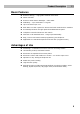
Product Description 1.1 Basic Features Exclusive design, – high-grade stainless steel finish. Water resistant Exclusive white button backlight – white LEDs Modularity – up to 54 buttons + keypad Up to 16 buttons per unit. Each basic unit has a space for camera and card reader build-in modules Increased protection through optional Vandal Resistant panel.
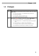
Changes 1.2 1.2 Changes Version Changes 2.0 A new version of the communicator firmware released in April 2007. Marking: FW:07-02-22 3.0 New voice functions – new parameters 974, 976 and 977 Dual tone detection New factory setting for parameter 951 Vandal resistant assortment upgraded New firmware version released in march 2011. Marking: FW:11.02.
2N® Helios Components and Associated Products 1.3 1.3 2N® Helios Components and Associated Products Basic and Extender Units Part No. 9135130E Basic unit 3 buttons Part No. 9135130KE Basic unit 3 buttons + keypad Part No. 9135181E Extender unit 8 buttons Part No. 9135160E Basic unit 3x2 buttons Part No. 9135160KE Basic unit 3x2 buttons + keypad Part No. 913582E Extender unit 8x2 buttons Part No. 9135310E Info panel A backlit button-less panel used for the telephone directory, house number, etc.
2N® Helios Components and Associated Products 1.3 Installation Accessories Part No. 9135331E Part No. 9135351E Part No. 9135361E Surface 1-module roof Wall mounting box with 1-module frame Wall mounting box with 1-module roof Dimensions 125×235×46 mm (W×H×D) Roof dimensions 129×240×41 mm (W×H×D) Wall hole 110×220×50 ±5 mm Wall hole 110×220×50 ±5 mm Part No. 9135332E Part No. 9135352E Part No.
2N® Helios Components and Associated Products 1.3 Increased Resistance Accessories Part No. 9135511E Part No. 9135511KE Part No. 9135515E Vandal resistant mask 3-button basic module + Vandal resistant wall mounting box Vandal resistant mask 3-button basic module with keypad + Vandal resistant wall mounting box Vandal resistant mask 8-buttons extending module + Vandal resistant wall mounting box Notes Use these covers to make the basic units or sets with up to 11 buttons more resistant.
2N® Helios Components and Associated Products 1.3 Video Accessories Part No. 9135210E In-built colour CCD camera PAL, resolution 420 TV rows, sensitivity 2 lux The camera can be built in any basic unit. In the case of poor light, the camera switches into the monochrome mode automatically. Supplementary infrared light. Horizontal/vertical tilting option. Part No. 9134147E 7" colour LCD monitor (TFT) The selected model features a composite video signal input with high sensitivity for long cabling runs.
2N® Helios Components and Associated Products 1.3 Card Readers 9134165E Chip card 91341612WE Built-in reader module for basic modules without keypad 91341611WE Reader set for basic modules with keypad Both readers has a memory for 748 users and RS485 interface. Technology: EM Marin 125kHz 9134166E Chip key fob Other Accessories Part No. 9135250E Part No. 91341481E Part No.
Terms and Symbols Used 1.4 1.4 Terms and Symbols Used Terminology Line pick-up/seizure/off-hook call start, line locked, busy. Line hang-up/clear call end, handset hang-up. DTMF dual tone multi-frequency signalling. PSTN public switched telephone network. Outgoing call 2N® Helios-telephone connection made, e.g. by a pressing a button. Incoming call telephone-2N® Helios connection. Programming mode 2N® Helios programming mode accessible from by dialling into the intercom only.
Terms and Symbols Used 1.4 Manual Symbols Safety Always abide by this information to prevent injury of persons. Warning Always abide by this information to prevent damage to the device. Caution Important information for system functionality. Tip Useful advice. Note Additional information.
2 2. Description and Installation This section describes the 2N® Helios product and its installation.
Button numbering – double-button set 7 15 23 31 39 47 1 4 8 16 24 32 40 48 2 5 9 17 25 33 41 49 3 6 10 18 26 34 42 50 11 19 27 35 43 51 12 20 28 36 44 52 13 21 29 37 45 53 14 22 30 38 46 54 Also applies to keypad sets Caution For the time being, Vandal resistant panels are available only for singlebutton sets with one extending module at most. Installing the info panel name plate, order No.
2.1 Before You Start Product Completeness Check Please check the contents of your delivery: 1 2N® Helios unit 1 Quick installation guide 1 User Manual on a CD 1 Hexagonal wrench 2/5 1 Transparent name plate foil of size A5 1 Spare name plate 2 Screws 2 Dowels Note If you have bought a complete „packet‟, the delivery may contain additional items including instructions for use and lists of available parts.
2.2 Mounting – Mechanical Installation Overview of Installation Types An overview of the installation types and the list of the required components are provided in the table below.
Indoor areas with a low relative air humidity (e.g., hallways, offices and other heated rooms). Indoor areas where humidity condenses on walls but never flows down the walls (porches, storage areas, industrial areas, e.g.). Outdoor areas where protection against rain and water flowing down the wall is provided (sheds, passages. e.g.). Outdoor application means: Environments where the product is exposed to rain or where water may flow down the walls (fence, outer wall of a building, e.g.).
6. If you use a roof module, fix its upper and side edges to the wall using silicone glue as shown in the figure to the right. Keep the following outdoor mounting principles: Always connect the backlight – it serves to equipment heating. Water must not flow in along or around the cables. Before closing the cover, carefully check all wires inside the cover for perfect closing. Make sure that all of the three loudspeaker holder feet fit into the board holes.
2.3 Electrical Installation Compatibility 2N® Helios is designed for conventional, analogue telephone lines and works regardless of polarity and line parameters.(Refer to the Technical Parameters) and uses tone (DTMF) or pulse dialling to be programmed. Normally, it is connected to a PBX line however It can also be connected to an analogue line or the GSM interface providing a wireless installation. Connection to Telephone Line Connect 2N® Helios simply using LINE terminals.
Fig.
Fig.
Description of Terminals GND This terminal protects 2N® Helios against static electricity damage. Switch 1 designed primarily for electric door lock control. SW1 These two terminals are connected to the 12V power supply with arbitrary polarity. The power supply can feed the electric lock too. LIGHT These two terminals are connected to the analogue telephone line with any polarity. LINE VIDEO + Video signal output – used only if a camera unit is included.
Typical Electric Lock Connection 2N® Helios contains a solid-state switch equipped with V-MOS transistors, which is able to switch both ac and dc regardless of polarity. Make sure that the current and voltage values do not exceed limits (refer to the Technical Data) and that the technical parameters of the lock and power supply are compatible. Electric door lock Power supply 12V AC or DC Tel. line Fig.
Typical Backlight Power Supply 2N® Helios features a high-quality white-LED name plate backlight. This backlight shows low power requirements, long life and even illumination of all name plates. If a standard 12 V electric lock (see above) is connected to 2N® Helios, the backlight can be powered using the lock power supply. Connect the power supply as shown in the figure.
Grounding Terminal Connection - Mandatory Any person that gets in contact with 2N® Helios may carry an electrostatic charge of several thousands of Volts. Drawing one‟s finger near to the 2N® Helios metal panel may result in spark discharge. The purpose of the grounding terminal is to protect the product against this discharge. The terminal carries the charge from the panel to the ground directly, not through the 2N® Helios circuits.
Separate Backlight and Electric Lock Supply Separate power supplies are necessary where the lock requires voltage higher than 12 V. In this case, an additional power supply (12V) must be used to illuminate the button backlight - see the figure below. Other reasons for such connection are the effort to minimise consumption from the back-up supply (which supplies the lock, not the backlight), or just that two weaker power supplies are available El. lock Supply AC or DC max.48V Supply AC or DC max.
2.4 Camera Installation The camera unit, Part No. 9135210E, can be built into any 2N® Helios basic unit during installation or as an option to be added later. You can also use the camera unit in combination with any Vandal resistant panel. It is a colour CCD camera with high resolution of 420 TV rows, with a monochrome night mode (infrared backlight hidden under the nameplates), and has a wide-angle pin-hole lens (90º diagonally) and a tilting hinge for manual direction adjustment.
2.5 Extending Module Connection 2N® Helios features an easy installation of extending button modules. Extending modules are connected using a single cable (included in every extender delivery) in a chain pattern (every additional unit is connected with the previous one). Each extending module has two connectors – an input connector (for connection towards the 2N® Helios basic unit) and an output connector (for connection of another, more remote unit).
Connector for next extender module connection Basic unit (open) Extender unit (bottom part) Removed upper part of extender module Fig.: 16–Button Extender Module Connection to Basic Unit Caution Extension modules must be interconnected by mounting jumper (tunnel), delivered together with each extension unit. This part is made from conductive plastic. If it is necessary to place extender unit at some distance, or if you lost the jumper, you must interconnect metallic covers by another way.
Button Numbering 7 15 23 1 8 16 24 2 9 17 25 3 10 18 26 11 19 27 12 20 28 13 21 29 14 22 30 Also applies to keypad sets It is possible to continue to 54 Button numbering – whole-button sets Button numbering – double-button set 7 15 23 31 39 47 1 4 8 16 24 32 40 48 2 5 9 17 25 33 41 49 3 6 10 18 26 34 42 50 11 19 27 35 43 51 12 20 28 36 44 52 13 21 29 37 45 53 14 22 30 38 46 54 Also applies to keypad sets Caution For the time being, Van
2.6 Buttons Labels – Insertion, Replacement Instructions 1. Remove the 2N® Helios metal cover. To do this, use a hexagonal key, unscrew the screw as shown in the figure and take the cover off. 2. Remove the name plates as shown in the figure using, e.g., a screw driver. 3. Remove the name plate inserts as shown in the figure. 4. Insert the labels printed on foil (see later). 5. Replace the name plate inserts. 6. Put the name plates back in the depression and click into position.
Label Material and Printing Every 2N® Helios delivery includes a sheet of transparent foil that can be easily printed, with a laser printer. Cut the printed foil into pieces and insert the labels into the name plates. Do not use paper to avoid water logging. Make sure that the text does not cover up the red arrows printed on the name plate, we recommend you to print the foil using a template (MS Word), available at www.2n.
2.7 Mounting - Completion 1. Remember to seal the 2N® Helios IP cable passage hole properly to avoid moisture in-leak and damage to electronics due to condensation. 2. Make sure that the wires inside 2N® Helios IP are not squeezed and insert the plastic top cover (a transparent plastic mould) carefully making its contacts plug into the electronics board connectors. Push the plastic cover into position moderately.
WRONG Gap between plastic cover and loudspeaker seal - water may leak in and damage electronics If the loudspeaker support is in a wrong position, the plastic cover may catch the support brim (see the arrow) and, if treated roughly, lead to component deformations. Leakage may arise, see the upper arrow. Properly tightened screw RIGHT The seal touches the plastic cover. Water flows out through a small hole (not shown in the figure). Note: Water does not affect the loudspeaker Mylar membrane.
3 ® 3. 2N Helios Configuration This section describes the 2N® Helios configuration.
Programming 3.1 3.1 Programming All 2N® Helios parameters, including the keypad ones, are set remotely using any tone-dialling telephone set (or a mobile phone). First call 2N® Helios and enter the programming mode. The access to this mode is service password protected. A voice menu is available in the programming mode and so you need not use this manual to program standard parameters. The menu is stored in the 2N® Helios memory in the default language.
Programming 3.1 Switch Password Programming Each switch can be controlled with up to 10 different passwords that are listed in the 2N® Helios memory. Passwords can be added to the list using functions 811 and 821 and deleted with functions 812 and 822 individually. The default status is a single password in the list, namely 00 for switch 1 and 11 for switch 2. These two special passwords cannot be entered from the 2N® Helios keypad.
Programming 3.1 Tip To check programmed values: enter parameter number and the parameter value and press for return to the main menu. , listen Deleting All Passwords, All Memories, Complete Initialisation The following three functions facilitate your programming by clearing all previous settings: 997 deletes the entire password list for both switches including passwords 00 and 11. 998 deletes memories of all buttons (01 - 54) plus Arrival/Departure and Day/Night passwords.
Full Parameter Chart 3.2 3.2 Full Parameter Chart Parameter Parameter Name (function) 011 to 546 All button memories Rang Default Note e Up to 16 digits blank Digits 0-9 can only be entered directly into the memories.
Full Parameter Chart Parameter Parameter Name (function) 3.2 Rang Default Note e 0-1 0= tone 1=pulse 40/60 Dialling timeout after pick-up 5-99 8= 0.8s Range of 0.5 - 9.9s 903 DTMF level 0-12 6 904 Automatic Multiple Number Dialling type 0-3 0= disabled for all buttons 906 Ticking into call 911 Count of rings before incoming call answering 1-99 912 Max. call duration 1-99 12 = 120s 913 Log-in timeout 1-99 3 915 Hang-up time between calls 5-99 15 = 1.
Full Parameter Chart 941 Minimum continuous tone time 10 99 20 = 2s 942 Minimum busy tone or pause duration 0-255 8= 0.08s 943 Maximum busy tone or pause duration 0-255 70 = 0.7s 944 Maximum tonepause difference 0-255 10 = 0.1s 945 Minimum count of busy tone periods 2-9 4 946 Dual tone detection setting 3.2 If the tone is longer, 2N® Helios hangs up. These parameters control the busy tone detection. They are used for call termination and automatic dialling.
Full Parameter Chart 3.2 971 Count of message repetitions 0-9 3 There is a 3-second pause between every two messages. 974 Communicator identification number 16 digits - The number enables communicator identification. 1st digit = type of message repeated after dialling. 2nd digit = type of message after confirmation. The following digits are used: 2 = identification (974) - loud speaking 4 = identification (974) - DTMF 5 = message as defined in par. 977 (after confirmation by par.
Full Parameter Chart 3.2 Explanation of Some Parameters 824 - Second Switch Synchronisation Set the parameter to a non-zero value to make switch 2 activate automatically with a defined delay if switch 1 is activated. Useful where two doors are close to each other. SWITCH 1 SWITCH 2 (The numbers in the figure are parameter numbers.
Full Parameter Chart 3.2 Explanation of Parameters 942, 943, 944 Busy tone tone time pause time par. 942 par. 943 Example: The busy tone in the figure above is considerably longer than the pause time. Therefore, set parameter 942 according to the pause, to 200 ms, e.g., and parameter 943 according to the tone, to 600 ms, for example. In this case, however, the default values can be maintained for both the parameters.
4 4. Function and Use This section describes the basic and extending functions of the product.
Function Description 4.1 4.1 Function Description From External User's View (Visitor) Like normal Doorbells, 2N® Helios buttons are provided with labels the visitor finds the appropriate button (e.g. Mr. Smith) and presses it this activates 2N® Helios to then dial the number pre-programmed for under that button, the visitor can then hear the ringing tone from the loudspeaker and the required (Mr. Smith„s in this case) telephone is ringing.
Function Description 4.1 From Internal User's View (Survey of Functions) Calling to 2N® Helios You call the appropriate extension and 2N® Helios makes the call and gives a confirmation tone after two rings (or as pre-programmed). Now you can speak and control the 2 switches, program 2N® Helios (see later), and listen to what is going on outside and speak to the calling party if desired. Door opening 2N® Helios contains a switch to which an electric lock can be connected (not included in this pack).
Function Description 4.1 Call extension 2N® Helios beeps 10 seconds before the call end to extend the call by 30 seconds press on your telephone (DTMF). You can use this function repeatedly. The visitor, however, cannot use this function! Programming The access to this mode is password-protected. For details refer to the Programming section. The voice menu considerably helps with programming 2N® Helios. Having entered the programming mode, you can also alter any parameter and memory settings.
Function Description 4.1 Call Termination Options - Summary 1. The busy or continuous tone *) after the call end. 2. The ringing tone *) after a predefined count of rings. 3. The subscriber „at the other end‟ pressed . 4. The preset maximum call duration has elapsed. 5. 30 seconds after the switch use has elapsed. 6. A 2N® Helios button was pressed during the call. 7. The keypad button was pressed during the call (can be disabled).
Function Description 4.1 Traditional Button Telephone Any number can be “dialled” in this mode. To dial, press , and to hang up use . These keys are typically provided with pictograms and . PSTN calls can be barred for a line in the PBX. The dialling type (tone, pulse) is selected in the programming mode. With pulse dialling, the character initiates (upon off-hook) transition to tone dialling – like on any other telephone.
Function Description 4.1 Keypad Operation Instructions - Summary Door opening – code lock Enter any valid password for switch 1 and Warning! Password 00 may not be used! Switch 2 activation: Enter any valid password for switch 2 and . . Warning! Password 11 may not be used! Traditional button telephone gets 2N® Helios ready to dial a number. … Dials a number. Transmits into tone dialling during pulse dialling. Transmits a character in tone dialling. Hangs up anytime during a call.
Function Description 4.1 Frequently Asked Questions About Keypad Function Can any of the switches be activated permanently? Yes, the additional switch can be activated by one password and deactivated by another. Is it possible to arrange for the switch to be activated during the whole call? Yes, additional switch can do it. Is it possible to use a single command to activate one switch first and the other later? Yes, it is possible to use parameter 824, Switch 2 delay.
Function Description 4.
Section for Advanced Users 4.2 4.2 Section for Advanced Users Automatic Multiple Number Dialling When you press a 2N® Helios button, you may find out that the called line is busy or the called party is absent. 2N® Helios is able to identify these situations and solve them by Automatic Multiple Number Dialling if one of three automatic dialling modes is enabled. Up to 6 numbers can be stored for each button.
Section for Advanced Users 4.2 If the ringing tone stops before the predefined count of rings is achieved and the call is thus very short (e.g. 2 seconds), it is not clear whether the call should be regarded as successful. Therefore, a new type of automatic dialling has been added - type 4. The difference is as follows: Type 3 regards such a call as successful only if the door is opened. Type 4 regards all such calls as successful.
Section for Advanced Users 4.2 Silent Automatic Multiple Number Dialling This mode fully conceals the fact that a telephone call is made. When a button is pressed, the loudspeaker is off and no PBX or dialling tone can be heard. The loudspeaker is switched on when the called subscriber confirms connection (by pressing on its telephone). Thus, a potential thief cannot establish whether the called person is in the building or not.
Section for Advanced Users 4.2 The above-mentioned commands may not be accepted due to poor connection if sent during a message. To avoid this, press the button during the time of silence (between messages). Survey of Messages The table below includes a survey of language versions for standard announcements. English is selected by default. To select another language, use parameters 976 and 977.
Section for Advanced Users 4.2 Arrival/Departure, Day/Night Modes 2N® Helios can identify easily where to „route‟ (switch) a call after a button is pressed. All you have to do is call 2N® Helios and enter the following: I‘m leaving: I‘m back: password password All buttons can be switched all at once by a common Day/Night password or individually by separate Departure/Arrival passwords.
Maintenance 4.3 4.3 Maintenance Cleaning If used frequently, 2N® Helios, especially the keypad, gets dirty. To clean it, use a piece of soft cloth moistened with clean water. We recommend you to obey the following principles while cleaning: Never use aggressive detergents (such as abrasives or strong disinfectants); Clean the device in dry weather in order to make waste water evaporate quickly. Label Replacement, Programming Status Changes For necessary steps refer to the preceding subsections.
5 5. Technical Parameters This section describes the technical parameters of the product.
Technical Parameters 5.1 5.
Technical Parameters 5.1 Other Parameters Switch – max. voltage 48 V AC, DC Switch – min., voltage 9 V AC, DC Switch – max. current 2 A AC, DC Backlight – rated voltage 12 V Backlight – max.
6 6. Supplementary Information This section provides supplementary information of the product.
Directives, Laws and Regulations 6.1 6.1 Directives, Laws and Regulations 2N® Helios conforms to the following directives, laws and regulations: Act No. 22/1997 Coll. Of January 24, 1997 on technical requirements of products and amendments to some laws Directive 1999/5/EC of the European Parliament and of the Council, of 9 March 1999 – on radio equipment and telecommunications terminal equipment and the mutual recognition of their conformity Governmental Regulation No. 426/2000 Coll.
Troubleshooting 6.2 6.2 Troubleshooting FAQ For tips concerning solutions of other potential problems see faq.2n.cz.
General Instructions and Cautions 6.3 6.3 General Instructions and Cautions Please read this User Manual carefully before using the product. Follow all instructions and recommendations included herein. Any use of the product that is in contradiction with the instructions provided herein may result in malfunction, damage or destruction of the product.
General Instructions and Cautions 6.3 Electric Waste and Used Battery Pack Handling Do not place used electric devices and battery packs into municipal waste containers. An undue disposal thereof might impair the environment! Deliver your expired electric appliances and battery packs removed from them to dedicated dumpsites or containers or give them back to the dealer or manufacturer for environmental-friendly disposal.
2N TELEKOMUNIKACE a.s. Modřanská 621, 143 01 Prague 4 Tel.: +420 261 301 111, Fax: +420 261 301 999 E-mail: sales@2n.cz Web: www.2n.cz DR1322 v3.