2N® BRI Lite/Enterprise User Manual Firmware Version 1.18.1 1.7 www.2n.
The 2N TELEKOMUNIKACE a.s. is a Czech manufacturer and supplier of telecommunications equipment. The product family developed by 2N TELEKOMUNIKACE a.s. includes GSM gateways, private branch exchanges (PBX), and door and lift communicators. 2N TELEKOMUNIKACE a.s. has been ranked among the Czech top companies for years and represented a symbol of stability and prosperity on the telecommunications market for almost two decades.
Content 1. Product Overview . . . . . . . . . . . . . . . . . . . . . . . . . . . . . . . . . . 5 1.1 Product Description . . . . . . . . . . . . . . . . . . . . . . . . . . . . . . . . . . . . . . . . . . . . . . 1.2 Safety Precautions . . . . . . . . . . . . . . . . . . . . . . . . . . . . . . . . . . . . . . . . . . . . . . . 1.3 Upgrade . . . . . . . . . . . . . . . . . . . . . . . . . . . . . . . . . . . . . . . . . . . . . . . . . . . . . . . 1.4 Terms and Symbols Used . . . . . . . . . . . . . . . .
7. Technical Parameters . . . . . . . . . . . . . . . . . . . . . . . . . . . . . . . 121 8. Supplementary Information . . . . . . . . . . . . . . . . . . . . . . . . . . 123 8.1 Troubleshooting . . . . . . . . . . . . . . . . . . . . . . . . . . . . . . . . . . . . . . . . . . . . . . . . . 8.2 List of Abbreviations . . . . . . . . . . . . . . . . . . . . . . . . . . . . . . . . . . . . . . . . . . . . . . 8.3 Directives, Laws and Regulations . . . . . . . . . . . . . . . . . . . . . . . . . . . . . . . .
1. Product Overview In this section, we introduce the 2N® BRI Lite / Enterprise product, outline its application options and highlight the advantages following from its use. Here is what you can find in this section: 1.1 1.2 1.3 1.4 Product Description Safety Precautions Upgrade Terms and Symbols Used 2N® TELEKOMUNIKACE a.s., www.2n.
1.1 Product Description The 2N® Enterprise / BRI Lite GSM gateway provides direct interconnection of the ISDN with GSM networks. It can also be used for direct interconnection of an ISDN PBX with a GSM network, ISDN telephone set and, via a terminal adapter, with an analogue apparatus or coin machine. The voice mode, i.e. outgoing and incoming calls, is the basic function of the gateway. Moreover, the BRI gateway provides connection to the VoIP-SIP networks.
2N® BRI Enterprise / 2N® BRI Lite Basic Features Integration of the best features of two communication technologies: ISDN and GSM VoIP–SIP telephony support with G.711a/u and G.
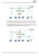
The gateway works as a dial-through router (using both the TE and NT ports in the DialThru mode) for calls to a mobile network, and a monitoring system, which, with the appropriate licence, sends SMS to the provider (in the case of line unavailability, e.g.). The 2N® BRI Lite GSM gateway contains just one ISDN BRI port and thus cannot work in the DialThru mode. It can be connected to a PBX on a trunk line or extension and route calls to the GSM/UMTS networks only – see the figure below.
1.2 Safety Precautions It is prohibited to use any transmitters, including the GSM/UMTS gateways, in areas where explosives are used, such as quarries. It is prohibited to use the 2N® BRI Enterprise / BRI Lite GSM gateways at petrol stations where mobile telephones are also prohibited. GSM phones may affect sensitive life-saving devices in medical centres. Therefore, it is forbidden to use GSM/UMTS devices, including the GSM gateways, in such facilities.
1.3 Upgrade The manufacturer reserves the right to modify the product in order to improve its qualities. In response to the customers' requirements, the manufacturer constantly improves the software contained in the product (firmware). For the latest 2N® BRI Enterprise / 2N® BRI Lite firmware version and the User Manual refer to the 2N web sites. Refer to the S. 2, Description and Installation, for a detailed description of the 2N® BRI Enterprise / 2N® BRI Lite firmware upgrade. Manual Version Changes 1.
1.4 Terms and Symbols Used Manual Symbols The following symbols and pictograms are used in the manual: Safety Always abide by this information to prevent persons from injury. Warning Always abide by this information to prevent damage to the device. Caution Important information for system functionality. Tip Useful information for quick and efficient functionality. Note Routines or advice for efficient use of the device.
2. Description and Installation This section describes the 2N® BRI Enterprise / 2N® BRI Lite product and its installation. Here is what you can find in this section: 2.1 2.2 2.3 2.4 2.5 Before You Start Brief Installation Guide Available ISDN BRI Extension Configurations IP Voice Transmission Types of 2N® BRI Enterprise Connection 2N® TELEKOMUNIKACE a.s., www.2n.
2.1 Before You Start Caution Make sure that you are equipped with all system components necessary for putting 2N® BRI Enterprise / Lite in operation (SIM card, ISDN phone and/or duly configured ISDN BRI line of your PBX or PSTN, an available Ethernet/USB socket and a PC for initial gateway configuration).
Caution 2N® BRI Lite has two RJ-45 connectors, which, however, are cross-connected into one ISDN BRI. Be sure to connect just one ISDN BRI line to make the system work properly. Which of the RJ-45 connectors will be used depends on the type of the equipment to be connected (NT/TE) and the interconnecting cable (cross/straight). Connector Lay-Out – Upper Side There are SMA female antenna connectors to each GSM/UMTS module on the 2N® BRI Enterprise / Lite upper side.
LED Indicators Power supply green light – mains powered no light – device switched off GSM/UMTS network green light – call in progress red light – error green flashing – network registration, SMS red flashing – module restart Red/green flashing – signal intensity indication ISDN port green light – 2 calls in progress green flashing – ISDN synchronisation/active call red light – ISDN disconnected red flashing – synchronisation of lower ISDN layers Ethernet port green light + no orange light – disconne
LED Indicators Power supply green light – mains powered no light – device switched off GSM/UMTS network green light – call in progress red light – error green flashing – network registration, SMS red flashing – module restart Red/green flashing – signal intensity indication ISDN port green light – 2 calls in progress green flashing – ISDN synchronisation/active call red light – ISDN disconnected red flashing – synchronisation of lower ISDN layers Ethernet port green light + no orange light – disconne
2.2 Brief Installation Guide Installation Conditions The following installation conditions have to be met for a proper installation: 2N® BRI Enterprise / BRI Lite is to be installed on a site with enough free space. 2N® BRI Enterprise / BRI Lite is to be mounted on a suitable vertical surface. For this purpose, a hanger is included in the gateway delivery, which is fitted to the wall using dowels and screws and used for gateway hanging.
No strong electromagnetic radiation is allowed on the 2N® BRI Enterprise / BRI Lite installation site. No strong electromagnetic reflections are allowed on the 2N® BRI Enterprise / BRI Lite antenna installation site. An inappropriate location of 2N® BRI Enterprise / BRI Lite or its antenna close to television, broadcasting and/or other rf-sensitive sets may impair the function of these sets.
Antenna Connection 2N® BRI Enterprise / BRI Lite is equipped with a SMA female antenna connector for all the GSM/UMTS modules. The external antenna should always be installed vertically on a site with a good wireless signal. Warning Tighten the antenna connector gently with your hand – never use a wrench! Being a source of radio frequency emissions, the 2N® BRI Enterprise / BRI Lite antenna should not be very close to the human body.
Power Supply Connection Use only the power supply adapter included in the delivery. Make sure that the electric distribution network voltage is in compliance with the data on the supply adapter plate before plugging the adapter and that the antenna is connected properly. If you connect the power supply without having connected the antenna, the GSM module transmitter may get damaged. Plug the supply adapter into the mains socket and only then connect the adapter connector to the gateway.
RJ-45 LAN Connector NT and TE Connectors ISDN devices are connected to the NT/TE connectors depending on the configuration of your telecommunications equipment. They are connected via a 4-wire passive bus with the aid of RJ-45 connectors. Refer to the figure below for the NT/TE connector pin lay-out. TE connector The figure below shows 2N® BRI Enterprise / BRI Lite connected as network termination (NT) – extension for your ISDN PBX or ISDN phone, i.e. your own equipment. 2N® TELEKOMUNIKACE a.s., www.2n.
The figure below shows 2N® BRI Enterprise / BRI Lite connected as terminal equipment (TE) – extension from the ISDN (PSTN), i.e. from your service provider. An example of the 2N® BRI Enterprise connection in the ISDN mode follows. Caution 2N® BRI Lite is equipped with just one ISDN BRI. Hence, two independent devices cannot be connected at the same time! 2N® TELEKOMUNIKACE a.s., www.2n.
2.3 Available ISDN BRI Extension Configurations You have to know the way of connection of your ISDN devices in order to configure your 2N® BRI Enterprise / BRI Lite GSM gateway correctly. For information on your ISDN type, check your ISDN extension provider's registration form or contact your telephone network administrator. Point-to-Point Configuration The Point-to-Point (EuroISDN with DDI) configuration interconnects directly one ISDN terminal (TE) and a network terminal (NT) (see the figure below).
2.4 IP Voice Transmission Speech Encoding Methods Voice transmission is strictly separated from signalling in VoIP networks. Modern VoIP networks mostly use the RTP (Realtime Transport Protocol) for voice transmission. The purpose of the RTP is only to transmit data (voice) from a source to a destination at real time. Codecs are used to save the channel data capacity. Codecs process the voice signal using variable algorithms to minimise the volume of user data.
Tip In the case of separated direct connection of your SIP Proxy and 2N® VoiceBlue Next, use the G.711 codec to achieve a high voice quality. SIP Components The following components are involved in the SIP message exchange: UAC (User Agent Client) – the terminal device client, which initiates SIP signalling. UAS (User Agent Server) – the terminal device server, which responds to SIP signalling from the UAC. UA (User Agent) – a SIP network terminal (SIP phones, gateways to other networks, etc.
2N® TELEKOMUNIKACE a.s., www.2n.
2.5 Types of 2N® BRI Enterprise Connection This subsection deals with the types of connection of the 2N® BRI Enterprise gatewa y to the main ISDN BRI extension. ISDN TE – 2N® BRI Enterprise Connection The connection type shown in the figure below provides communication via a GSM/UMTS gateway without PSTN connection. The ISDN telephone sets are connected to the NT port of the GSM gateway, while a mains adapter simulating power supply from the PSTN is connected to the TE port.
With multiple GSM gateways, the connection lay-out is as follows: 2N® TELEKOMUNIKACE a.s., www.2n.
2N® BRI Enterprise Connection as DialThru Router This type of connection saves one BRI port to the PBX. Incoming PSTN calls are treated by the GSM/UMTS gateway in the DialThru mode while outgoing calls are routed according to the LCR table. The figure below shows the gateway as a DialThru router for the Point-to-Multipoint extension. Calls are routed automatically into GSM, UMTS or ISDN based on the internal LCR rules. 2N® TELEKOMUNIKACE a.s., www.2n.
3. Making Calls via BRI Gateway This section describes the call routing techniques via an ISDN BRI GSM gateway. The purpose of the settings is to improve your call efficiency and cut your call costs. Here is what you can find in this section: 3.1 Supported 2N BRI Gateway Functions 3.2 Call Routing Principles 2N® TELEKOMUNIKACE a.s., www.2n.
3.
3.2 Call Routing Principles 2N® BRI Lite The gateway is equipped with one BRI ISDN and one VoIP-SIP ports. You can select one of the following incoming call processing modes for each of the ports via the web interface: Use LCR table – in this case, calls with be routed as set in the LCR table Reject calls – all incoming calls will be rejected Route to port – all calls will be routed to the selected port without change If your BRI gateway is connected to a PBX subscriber line, you can activate DTMF.
Tip 2N® BRI Enterprise / BRI Lite can also route outgoing calls into the GSM/UMTS networks according to the B-channel used. In that case, the GSM/UMTS module is paired with a specific B-channel of the ISDN BRI line. 2N® Mobility Extension 2N® Mobility Extension (ME) is a function that turns your mobile phone into an SIP phone taking advantage of all the PBX functions.
Fig. 1 shows routing of calls in the case of absence of a subscriber in the VoIP network. Subscriber A calls subscriber B, for whom the 2N® Mobility Extension function has been permitted with the active “Follow me” function. Subscriber B does not answer the call in the VoIP network and so the call is rerouted to its mobile telephone. “SMS at no answer” function In the case of a missed call in the VoIP network, the 2N® Mobility Extension provide s sending of an information text announcement.
Figure 3: Call Forwarding Function In Fig. 3 subscriber A is talking to subscriber B, for whom the 2N® Mobility Extension has been permitted. Subscriber A would like to be forwarded to subscriber C. For this reason, subscriber B holds the call with A (7* in the default setting ), dials the number of subscriber C, terminates dialling with the dialling end character (# in the default setting), notifies subscriber C of the call to be forwarded and hangs up to forward the call.
Figure 4: Quick Call Forwarding Function Correct ME configuration Connect the GSM gateway to your PBX/SIP Proxy. Check whether the 2N® Mobility Extension licence key has been entered correctly. Enter all ME users in the Gateway configuration Mobility Extension menu. Enter the prefix matching the ME user mobile number in the Gateway configuration prefixes menu. LCR Table The LCR (Least Cost Routing) table is the key telephone cost cutting tool.
Poznámka Count of digits defines the minimum count of digits to be dialled. Hence, a call is successful if the count of the called number digits is equal to or higher than the value set in the Count of digits. The Count of digits does not include the digits removed from/added to the number in the Table of replaced prefixes. The Count of digits set in the Table of accepted prefixes has a higher priority than the Default count of digits.
If the selected GSM module is busy or has a low credit, the preceding step is repeated and the next LCR row is checked. In case the selected GSM module is free and has a sufficiently high credit, the GSM gateway starts dialling the GSM number. If the calling subscriber number has an unknown prefix or all routes are busy, the GSM gateway rejects the call setup request. An outgoing call is not billed until the called party answers the call.
DISA Message With DISA activated and DISA welcome note recorded, the message is played to every incoming call whose CLIP is not included in the AutoCLIP table. After playing, the gateway waits for the first DTMF digit for the time period defined in the Incoming GSM calls – DTMF dial timeout table.
4. First Launch Having completed the physical installation, get acquainted with the factory settings and operation of the 2N® BRI Enterprise / BRI Lite gateway. Here is what you can find in this section: 4.1 4.2 4.3 4.4 4.5 Ethernet Interface Licence Firmware Version Factory Reset Basic Configuration – Step by Step 2N® TELEKOMUNIKACE a.s., www.2n.
4.1 Ethernet Interface The BRI gateway can be fully configured via the web interface at http://IP_gateway_address. Make sure that a device equipped with a web browser (PC, NB, Tablet, etc.) has been connected for successful connection to the BRI gateway configuration interface. The device also supports configuration via an extended AT command set on the Telnet interface (IP port 23). Tip The device also supports configuration via an extended AT command set on the Telnet interface (IP port 23).
MAC Address The BRI gateway has a unique, factory-set MAC (Media Access Control) address. Refer to the rear side label of your device or the gateway web interface for the MAC address. The MAC address can be user-changed. Tip If you use DHCP, you are advised to set permanent assignment of one and the same IPv4 address to the defined MAC address to avoid unexpected change of the gateway IPv4 address and subsequent VoIP-SIP setting errors. 2N® TELEKOMUNIKACE a.s., www.2n.
4.2 Licence The BRI gateway can contain different licence keys depending on the Part No. Refer to the Gateway control – Firmware/Licence section via the web interface for the current licence key status. Use this section to download a new licence key into your gateway in order to change the current software licence status. Caution The 2N® BRI Enterprise / BRI Lite gateway can contain time-limited software licences (for SIP signalling, Mobility Extension, etc.).
4.3 Firmware Version Upgrade your 2N® BRI Enterprise / BRI Lite gateway with the latest firmware version available for this GSM gateway type before installation. Refer to www.2N.cz for the latest firmware version. Warning Use the firmware certified for this GSM gateway type only to avoid irreversible damage to your system! Download the new firmware version comfortably using the gateway configuration interface as follows: Connect the PC and gateway to the Ethernet.
4.4 Factory Reset Should you forget your password or set the IP interface incorrectly, you can reset the factory values. Press the Reset button right to the BRI ISDN connector for a rather long time to reset the default values. Doing so, you reset all the factory configuration values for all the parameters including those related to the Ethernet interface and access data.
4.5 Basic Configuration – Step by Step This subsection helps you put your BRI gateway in operation for the first time. Refer to the paragraphs of S. 3 for more detailed settings. Install the GSM gateway as instructed in Subs. 2.2. Remove the SIM cards or insert the PIN-disabled SIM cards before the first launch. Connect the GSM gateway to the Ethernet to be able to get connected to the address mentioned in Subs. 4.1, page from the web interface.
5. Introduction to Configuration Interface This section introduces the configuration interface of the 2N® BRI Enterprise / BRI Lite product. Here is what you can find in this section: 5.1 Configuration Web Interface Gateway Control Gateway Configuration Messaging SMTP/POP3 Basic Configuration – Step by Step SMPP Basic Configuration – Step by Step Monitoring List of SNMP traps Others 2N® TELEKOMUNIKACE a.s., www.2n.
5.1 Configuration Web Interface Essential Data The 2N® BRI Enterprise / BRI Lite web interface supports the following web browsers: MS Internet Explorer v9 Mozilla Firefox v4 and higher Any other web browsers may cause troubles. The recommended screen resolution is 1280x1024 and colour quality 32bit and higher. The configuration interface is available in the English language version only at present. Tip Use the F11 key to display the full-screen mode.
Caution You are recommended to change these default login data upon the first login to increase security of your system significantly. Web Icons Caution Remember to press the Save settings button to save the changes in order to avoid loss of new data after leaving the current configuration window! [4]Set the time limit value in the Gateway – Web configuration – Auto logout section. Home Page Upon login, you get onto the home page (see the figure below) of the Gateway section.
SIM client – for connection to the 2N® SIM Star system. SMS – for receiving/sending SMS via the web interface. Messaging – for receiving/sending SMS via SMPP or SMTP/POP3 Monitoring – for gateway monitoring via SNMP Utils – including extending system tools (Network capture, Report capture). Management – for firmware update, license upload and configuration upload/download.
Gateway Control Gateway control helps you: Monitor the current state of each GSM gateway parts; Check and set the GSM gateway licence; View and save the LOG file and CDR. Firmware / Licence Use this window to display information on the gateway licence status, firmware and bootware versions and Ethernet interface MAC address. Use the web interface to download a new licence via Management Licence. Firmware version – displays the current firmware version for the GSM gateway connected.
Caution By inserting a new licence code you restart the GSM gateway and discontinue all the currently made calls! Date / Time Use this window to set the current date and time for your gateway. Tick Synchronise with local PC to set the time a date items automatically according to your PC data. Caution The internal power source keeps the internal clock source running for a few hours only! Therefore, check the current gateway date and time after long BRI gateway disconnection! 2N® TELEKOMUNIKACE a.s., www.
Voice Messages This window is used for recording, checking and downloading messages. Supported format is PCM–Alaw, Mono, 8000 Hz, 8 bits.
Refer to Subs.7, page for details on LOG records. CDR File The CDR file window helps read out the Call Data Records (CDR) of the gateway. The bottom part of the window includes icons for saving the CDR into a file and refreshing the CDR listing in the web window. Refer to Subs. 6.6 Call Data Records (CDR) for more details on the CDR format. Caution The maximum capacity is 100,000 call records.
Statistics The window displays the current statistic data on calls. There are LOG file saving and LOG listing updating icons in the lower part of the window. Refer to Subs. 6.7, page for the statistic data format details. Current call info The window displays the currently made calls. There are LOG file saving and listing updating icons in the lower part of the window. Connection state The window shows the state of all available configuration sessions.
Gateway Configuration System Parameters General Saving call data (CDR) – define the call types for which the GSM gateway shall store information in the CDR. Gateway ID – provides 2N® BRI gateway with a numerical code in the CDR in case multiple devices generate CDRs in the network. Number for remote control. Summer / winter time Automatically move to summer/winter time – enable automatic GSM gateway system time change for winter/summer time format transition. Date of move to winter time [dd.
Caution A PIN–active SIM card with a PIN value other than that set in the GSM gateway configuration will be blocked by the gateway with the 'pin–err' cause. Enter the correct PIN on your mobile phone to unlock the SIM card! End of dialling (empty=off) – set the DTMF code for DTMF dialling end for DISA incoming calls. The default value is „#". List of emergency numbers The window displays a list of emergency numbers, which are normally routed to the BRI interface.
SIP protocol settings Use CLIP from INVITE field – define that CLIP from the 'Contact' or 'From' field shall be used for call routing to GSM/UMTS. Send 180 ringing instead of 183 session progress. Send 200 OK instead of 180/183. Send 200 OK and BYE when rejected from GSM. Send 200 OK on REGISTER request – virtual registration of device in 2N® BRI gateway (for registration requiring equipment). Replace CLIP from GSM with Caller ID. Deny DTMF according to RFC2833. Forward DTMF for ME.
Tip If you keep the default values (0.0.0.0), 2N® BRI gateway will receive requests from any IP address. SIP proxy (GSM IP) – the SIP proxy IP address to which 2N® BRI gateway turns in the case of GSM incoming calls. SIP registrar – SIP registration server IP address.
ISDN Parameters Use this window to set the BRI ISDN port parameters. The appearance and count of the parameters may be different in 2N® BRI Lite and 2N® BRI Enterprise due to different counts of ISDN BRI ports. BRI mode selection Mode – set the BRI1 and BRI2 (for 2N® BRI Enterprise only) ports. BRI1 and BRI2 TEI Address – set a fixed TEI address for connection of port(s) in the Point–to–Point mode. MTP – activate assignment of the dynamic TEI address (Point–to–Multipoint mode).
INFO (7) Receive dial number from Subaddress – use this parameter to receive dialling from the subaddress element instead of standard CDN. Don't send Connect ACK on TE – use this parameter to enable/disable sending of the CONNECT ACK message to the TE port. Use CLIR if requested from ISDN (SETUP) – enable automatic CLIR resending to GSM/UMTS if required so by the ISDN. Tone signalling for calls from ISDN Dial tone to BRI1 with empty SETUP – set the dial tone type to be generated by the BRI gateway.
BRI2 alerts Still activated ISDN layer 1 – enable/disable keeping of ISDN layer 1 active. Still activated ISDN layer 2 (SABME/UA) – enable/disable keeping of ISDN layer 2 active. Send SMS at state changes – enable/disable alert sending upon BRI1 state change. BRI common settings Timeout for ISDN line deactivation detection [s] – an SMS alert on BRI1/BRI2 deactivation is sent after this timemout.
Holiday list List of days on which calls will be routed like on weekends in the LCR. DTMF settings Minimum delay between two identical DTMF characters [s/100] received. Tone detector settings The GSM gateway can automatically detect user defined tones transmitted by GSM/UMTS for setting up outgoing calls to the GSM/UMTS networks. In general, they are tones of a transferred number.
Caution If the Generate busy tone function is enabled, the duration of outgoing calls billed by the GSM/UMTS provider will be extended! Error GSM/UMTS causes Set the ISDN release cause for each of the below mentioned statuses. Every call that meets any of the below mentioned requirements, will be rejected with a user defined cause (the ISDN cause number will be translated to VoIP as a SIP code as defined below).
Conversion table: ISDN cause value 1 3 6 16 17 Unallocated number No route to destination Channel unacceptable Normal call clearing User busy SIP code 410 404 503 BYE 486 18 No user responding 480 19 No answer from user 480 21 22 27 28 29 31 34 38 41 42 44 47 50 55 57 Call rejected Number changed Destination out of order Address incomplete Facility rejected Normal, unspecified No circuit available Network out of order Temporary failure Switching equipment congestion Requested facility not subscrib
Others Text of SMS at no answer – edit the text of the SMS to be sent to the calling party in case of no answer (if the function is active). The %N string will insert the CLIP received from VoIP in the SMS text. Text of SMS for all calls – complete this parameter to make the GSM gateway send SMS to every called party regardless of whether or not the call was successfully connected. The %N string will insert the CLIP received from VoIP in the SMS text.
Generate virtual ring tone – enable/disable generation of the virtual ringing tone into the VoIP interface. Call length counting – define whether call minutes or seconds shall be counted. BTS lock – identify the BTS to which the GSM modules shall log in. Restart the selected GSM modules to execute the changes. Caution The BTS lock service work with specific GSM modules only (Q55)! If you set a wrong BTS lock, the selected GSM module(s) will not log in to GSM.
String Note Roaming disabled 2300 Roaming disabled (five digits at least) 23002 Roaming enabled for the 23002 (MCC+MNC) network 230XX Roaming enabled for the 23000 – 23099 (MCC+MNC) network XX001 Roaming enabled for the 00001 – 99001 (MCC+MNC) network XXXXX Roaming enabled for any network Note Before enabling roaming, please use your mobile phone to make sure that the GSM/UMTS searching priorities have been set properly on the SIM card.
Time limits There are two SIM use time limits in a GSM group. Call tariffs Use this function to assign up to four independent free minute counters to a group of GSM modules (SIM cards), e.g.: Tariff 1 = free minutes for calls to own GSM/UMTS network; Tariff 2 = free minutes for calls to other GSM/UMTS networks; Tariff 3 = free minutes for calls to fixed network; Tariff 4 = free minutes for calls within a closed user group (VPN).
General settings Mode – set how the gateway shall process incoming calls from the GSM network. Reject incoming calls – all incoming calls from the GSM network are rejected automatically. Ignore incoming calls – all incoming calls from the GSM network are ignored. The calling party hears the check ring tone. Accept incoming calls + voice message – incoming GSM calls are accepted by the gateway and, if programmed so, DTMF with a voice message is activated for them.
Send CLIP from GSM/UMTS to VoIP Transfer CLIP from GSM/UMTS – enable/disable the function. Separating char – set the separator for the SIM card CLIP and ID of the extension to be called. Modify – modify the extension ID. Caution The Send CLIP from VoIP to GSM service must be supported by the GSM/UMTS provider's network. Otherwise, the call may be rejected by GSM/UMTS. Others Time to keep CLIP in table – set the record keeping time for AutoCLIP routing.
Note The number to be dialled to the GSM/UMTS network must meet the Count of digits condition. For VoIP calls, the count of digits to be dialled must be equal to or higher than the value set in the Count of digits. For GSM/UMTS calls by overlap dialling via the BRI NT/TE interface, the Count of digits defines the maximum count of the digits to be dialled. For GSM/UMTS calls by block dialling via the BRI NT/TE interface, the Count of digits is ignored.
to GSM basic settings), the GSM gateway automatically terminates the call and seeks for another call setup way. If this parameter is activated, the GSM gateway ignores the tone detection results and sets up a call when this is the only possible call establishing way. Note If you use tariff routing, set the tariffs properly in the GSM outgoing groups subsection The maximum count of LCR table records is 256.
Caution Saving wrong values, e.g. DHCP enable, may result in making the 2N® BRI gateway configuration part inaccessible. In that case, reset the GSM gateway to factory values; refer to Subs.4.1. Tip If the gateway is in the DHCP client mode, the current values obtained from the DHCP server are displayed in the IP address, Subnet mask and Default gateway items. Login Configuration Use this window to set the access password and name for the 2N® BRI gateway web interface.
Messaging This group helps: Set the GSM gateway to send/receive SMS via SMTP/POP3 or SMPP Define the routing rules for incoming and outgoing SMS messages Check the GSM gateway SMS database filling capacity Caution This service is file-licensed. Refer to Management Licence key for the current GSM gateway licence details. Modules Grouping Global settings SMS server enabled – enable/disable the SMS server at the GSM gateway (keep disabled if you select another SMS processing method).
Caution The count of user accounts is file-licensed. Refer to Management Licence key for the current GSM gateway licence details. Users This section helps you manage the SMS users. Select a communication protocol for user adding (SMTP/POP3 or SMPP). 2N® TELEKOMUNIKACE a.s., www.2n.
Add user User group – assign the user to a User group. User full name – define the system user name. Replace dial for outgoing SMS – define the number (CPN) to which the user's outgoing SMS messages shall be sent. Access type – select the communication protocol for SMS processing: Email (SMTP/POP3) – use SMTP for SMS sending and POP3 for SMS receiving. SMPP (SMSC) – set the GSM gateway into the 'SMS centre' mode. SMPP (ESME) – set the GSM gateway into the 'ESME External Short Messaging Entity' mode.
User Group This section helps you edit the User group and set the routing rules for the group's incoming and outgoing SMS. General settings Set the basic parameters for SMS sending via SMTP/POP3 or SMPP. Optional informations Description – set the User group details. Identical SMS limit – set the check of identical SMS messages, i.e. sequentially sent messages with identical SMS PDUs. When the set limit is exceeded, the excessive SMS messages are discarded without being sent.
Tip The following options are available for subject modification: %% – Insert the "%" character %n – CLIP number %u – Login name %f – User full name %d – Date and time %s – SIM IMSI %m – Module %g – Group SMTP - Maximum SMS per email – set the maximum count of SMS messages to be sent within one Email message. Any characters exceeding the set length will be ignored. SMTP - Add "From" to SMS – add 'From' from the Email message to the outgoing SMS.
SMPP address modification Source address of message incoming from SMPP – set how to modify the message sender ID received via SMPP. Never replace original address Replace if the original address is empty Always replace original address address – enter sender's new ID TON – type of number NPI – numbering plan indicator Destination address of message incoming from SMPP – set how to modify the message addressee telephone number received via SMPP.
Incoming SMS routing This section helps you set the incoming SMS routing rules, which are included in the incoming SMS routing table. Add record Disabled – enable/disable the selected routing rule. Message from SMS group – select the SMS group that receives the SMS. Action type – select the action for the received SMS: Autoclip routing – the incoming SMS will be routed according to the AutoCLIP table records. Deliver to user – the SMS will be delivered to the selected user.
Outgoing SMS routing This section helps you define the outgoing SMS routing rules, which are included in the outgoing SMS routing table. Add record Disabled – enable/disable the selected routing rule. Message to SMS group – select the SMS group via which the SMS will be sent. Action type – select the action for the outgoing SMS: Submit from user – enable sending SMS from the selected user. Submit from all users – enable sending SMS from all the SMS group users.
Control This section helps you monitor the system. It includes storage filling information and AutoCLIP records. SMS queues The subsection displays the current SMS storage state. Incoming SMS database The subsection displays current information on the incoming SMS storage filling percentage and maximum count of incoming storage records. Caution The POP3 protocol enables you to set how long a copy of the loaded message shall be kept in the SMS server.
AutoCLIP routing table The window displays the current state of the AutoCLIP table. 2N® TELEKOMUNIKACE a.s., www.2n.
SMTP/POP3 Basic Configuration – Step by Step This section helps you define the 2N® BRI basic parameters for SMS sending/receiving via SMTP/POP3. Read the Messaging subsection carefully before setting details. Figure 1 shows sending/receving SMS via SMTP/POP3. Having created user accounts in 2N® BRI, the users can access the accounts via the e-mail client and send SMS messages to 2N® BRI via SMTP. The gateway receives the messages and resends them to the GSM users according to the predefined routing rules.
3. a. Set the user domain. The domain is automatically assigned to the user name in the selected User group and represents the user e–mail address. Example: Suppose a user was created in step 2.c with Login name: USER and domain Domain: email.com, then the e-mail address of the user with the right to access the SMS server will be USER@email.com. The @ character is completed automatically and is not included in the Domain: field. 4.
SMPP Basic Configuration – Step by Step This section helps you define the basic parameters for SMS sending/receiving via SMPP in 2N® BRI. Read the Messaging subsection carefully before setting details. Figure 1 shows sending/receiving SMS via SMPP. Having created user accounts in 2N ® BRI, the users can send/receive SMS via SMPP. The figure shows an example with two SMSC accounts created in 2N® BRI (to the right).
3. c. Set Deliver to user to to define the SMS receiving user. 4. Create the outgoing SMS routing rules in the Messaging User Group General settings Outgoing SMS routing Add menu: Enable the SMS server in the Messaging Modules grouping SMS server enabled menu. a. Set the SMS group via which the outgoing SMS will be routed in the Message to SMS group menu. b. Select the Action type to define how to process outgoing SMS. Example: Set Action type: Submit from user to send SMS from selected users. c.
Monitoring This section helps you configure sending of SNMP traps. Download the list of available traps, i.e. the MIB table, from the gateway web interface. The main purpose of SNMP monitoring is to observe your GSM gateway states continuously and send state information to the defined IP addresses whenever an error occurs. Refer to the List of SNMP traps for the list of all SNMP traps sent by 2N® BRI.
Servers First SNMP server – the addressee's primary IP address and transport port for SNMP traps (default port = 162). Please make sure that the parameters have been completed correctly to avoid SNMP malfunction. Second SNMP server – the addressee's secondary IP address and transport port for SNMP traps (default port = 162). If these parameters are correctly completed, the SNMP traps will be sent both to the primary and secondary IP addresses.
List of SNMP traps Type VoIP GSM Text VoIP SIP line is not registered VoIP SIP line is registered BRI 1 link unplugged, layer1 deactivated BRI 1 link plugged in, layer1 activated BRI 1 link layer 2 not established BRI 1 link layer 2 established BRI 2 link unplugged, layer1 deactivated BRI 2 link plugged in, layer1 activated BRI 2 link layer 2 not established BRI 2 link layer 2 established First GSM module: ERROR First GSM module: OK First GSM module has too strong signal level First GSM module decreased u
Others SMS This subsection helps you send and receive SMS via the modules. Tip You can also use the SMS user account for SMS sending/receiving. Refer to the Web Configuration subsection for SMS user configuration details. Utils This section provides extra functions of the GSM gateway. At present, the GSM gateway offers the Ethernet interface tracing (Network trace) and gateway communication tracing functions. These functions help detect gateway installation troubles (SIP communication debugging).
When the new firmware file has been uploaded successfully, the GSM gateway will be restarted automatically. Licence key This section helps you upload the licence file/code to 2N® BRI and provides information on the current licence file. Refer to Gateway Control for more details. Caution By inserting a new licence code you restart the GSM gateway and discontinue all the currently made calls! Restart This section provides forced restart of the BRI gateway connected. 2N® TELEKOMUNIKACE a.s., www.2n.
Configuration download Use this window to download the current BRI gateway configuration. The saved file has the following format: CFG–M202–gateway_serial_number–rrrrmmdd–hhmmss.tar Configuration upload Use this window to upload new configuration to the BRI gateway. The Ethernet interface values and access data remain unchanged! Warning Upload a well–known configuration file intended for the selected GSM gateway to avoid GSM gateway error and subsequent factory restart.
6. Advanced Configuration Communication with the 2N® BRI Enterprise / BRI Lite gateway is via the LAN. This connection provides uniform gateway configuring by AT commands. Here is what you can find in this section: 6.1 6.2 6.3 6.4 6.5 6.6 6.7 6.8 LAN Communication Setting GSM Gateway Behaviour List of Terminal AT Commands Status Messages LOG Files Call Data Records (CDR) SMS Data Records (SDR) Statistics - Description 2N® TELEKOMUNIKACE a.s., www.2n.
6.1 LAN Communication Setting First set the 2N BRI gateway IP address to communicate with the gateway via your LAN successfully. To do so, configure the Ethernet interface; refer to Subs.4.1. Use any of the available programs (HyperTerminal, Telnet, Putty, etc.) for communication and configuration with the following data: IP address:address set by you Port:23 (Telnet) 2N® TELEKOMUNIKACE a.s., www.2n.
6.2 GSM Gateway Behaviour The gateway behaves as an ANSI terminal with echo. Commands are entered in the text format. Upon login, the gateway reports itself with OK. If not, enter the at comma nd and press . A correctly connected gateway should answer OK. In such case, the gateway starts communicating with a dialogue shown in the figure below. Enter the user name, press and, when being asked so, enter the access Password. . 2N® TELEKOMUNIKACE a.s., www.2n.
6.3 List of Terminal AT Commands By default, all these commands start with AT. (Note: Some of the AT commands listed below may not be available in the current firmware versions.) Basic AT Commands The following command list is intended for all GSM gateways from 2N® that are based on the same SW architecture. Some of the AT commands may be inaccessible for the BRI gateways.
Configuration AT Commands System Settings %S85=sms – no answer sms text (max 63 chars) %S90=mode – operating mode of GSM module allocation (0=cyclic mode, 1=locked mode, 2=smart mode – according to already called minutes) (for 0 and 2 set LCR group = 3 (any)) %S91=buf,id – cdr mode (b0=outg, b1=inc, b2=failed, b3=moninfo) unit id (0=off, 1..255) %S92=rep – report mode (b0=states, b1=tstamp, b2=smp, b3=lay2, b4=select) %S98=pin – sim pin (max 7 digits) %S99=dd.mm.yy.w/hh:mm:ss – set date/time (w=1..
ISDN Settings %I00=xxx – pri1 protocol/mode: NT,TE,NT/S,NTNT (pri2 = TE,NT,SY,NT) For FW:2_03_15 only NT and NT/S (sync received from TE port) %I01=tei,mtp tei,mtp = 0..63,0 – .fixed tei,ptp tei,mtp = 64,0 – .dynamic tei,ptp tei,mtp = 64,1 – .fixed tei,mtp %I05=c1,c2,c3,c4 – cause codes for failed calls c1=dial timeout (TIMEOUT=120) c2=dis.prefix (REJECT=21) c3=req.mod/grp not ready (TEMPFAIL=41) c4=pref grps not ready (CONGEST=42) %I06=sack,proc,prog,ale – prog.elem (0=off,1..
GSM Settings %G02=mode,atms,afms – tc35 mode (2,4) atms/afms gain (+5dB=3,+2.5dB=1,0dB=0,–2.5dB=2,–5dB=4) %G05=delay – dtmf space delay (1..99 sec/100) %G06=mmdd,..mmdd – holiday list (0101=1st jan, 1231=31st dec) %G07=mmdd,..mmdd – holiday list2 %G08=delay,min,max,tout – gsm call delay (0..10 sec), dial min/max (0..20) dial tout (0..
Network List Parameters %N#0=opx/npx – list of old/new main–prefixes (max 47 chars) %N#1=pref/dig – list of prefixes/digits–to–end (max 63 chars) %N#2=pref/dig – pref. list extension (max 63 chars) %N#3=pref/dig – pref. list extension (max 63 chars) %N#4=pref/dig – pref. list extension (max 63 chars) %N#5=pref/dig – pref. list extension (max 63 chars) %N#6=pref/dig – pref. list extension (max 63 chars) %N#7=pref/dig – pref.
Control SMS AT^SX=ch – (sms listing) request to list all SMS messages and status confirmations saved on SIM card. Possible answers:: *smserr (busy,list) or *smsinc (ix=1..255) for each saved SMS or status SMS messages, end of list or empty SIM card – *smsinc (ix=0). AT^SR=ch,ix – (sms read) request to read SMS or status SMS saved in SIM card. Possible answers: *smserr (busy,read) or *smspdu AT^SD=ch,ix – (sms delete) request to delete SMS message (or status SMS message).
6.4 Status Messages ISDN Layer 1 Message Status ID 0 Name DEACT Description Deactivation – no signal received 1 ACTIVE Activation – full synchronisation achieved (frame,multiframe,crc) 2 SIGNAL Signal received – no synchronization 3 SYNC Signal received – only partial synchronization (frame) ISDN Layer 2 Message Status ID 0 Name NOTEI Name acc. to ITU–T Q.
ISDN Layer 3 Message Status ID Name Name acc. to Q.
Management Message Status ID 0 Name INIT Initialization upon BRI reset Description 1 IDLE Activation – rest status, necessary for layers 2 and 3 2 DISC Deactivation 2N® TELEKOMUNIKACE a.s., www.2n.
GSM Layer Statuses GSM Layer 2 Message Status ID 0 Name INIT Description GSM module initialization start Follows PINREQ 1 SIM0 Module switch to internal SIM card INIT 2 PINREQ Module PIN request PINSET 3 PINSET PIN value sensing to module INFO 4 BLOCK Module blocked temporarily or permanently (see Layer 2 information) INIT 5 SETUP Module configuration running IDLE 6 SLEEP Module sleep running (transition to BLOCK status) BLOCK 7 NWAIT Awaiting GSM log–in SETUP 8 IDLE Rest st
GSM Layer 2 BLOCK Message Status ID Name Description Blocked by AT&G command, terminated by module, board or system reset 41 (block) 42 Netw–reg GSM log–in refused (not activated SIM), next attempt in 5..60 minutes 43 Clir–err CLIR activation request refused, next attempt in 2..
GSM Layer 3 Message Status ID 0 Name NULL Rest status, ready for call Description 1 CINIT Request of call to GSM (from Layer 4) 3 OPROC Call to GSM is connected 4 CDELIV Call to GSM is ringing 6 CPRES Indication of call from GSM (from Layer 2) 7 CRECV Call from GSM is ringing on ISDN interface 9 IPROC Call from GSM is processed by ISDN interface 10 ACTIVE Connected call 11 DISREQ Disconnection request (to Layer 2) 12 DISIND Indication of disconnection (from Layer 2) 19 RELREQ
Layer 4 Message Status ID 0 Name NULL Rest status, ready for call Description 1 MORE Call request received from GSM or ISDN, awaiting further dialling or timeout 2 SETUP Call request sent to opposite interface 3 PROC Call request confirmed, awaiting call answer 4 ACTIVE Connected call 5 DISC Call disconnection in progress 2N® TELEKOMUNIKACE a.s., www.2n.
Command Shell Statuses Command Row Message Status ID 0 Name IDLE Description Rest status, awaiting AT commands 1 REQUEST Communication with GSM module upon AT&G command is displayed 2 REPORT Active tracing 3 LOGFILE Content of log file is being written out 4 CALLFILE Content of call file is being written out 5 CALLREAD Call file records are read 6 AUTOFILE Content of incoming call autorouting chart is being written out 7 QUERY (not used so far) 8 SCREEN (not used so far) 9 MATRIX
Records of Events and Calls Records on Events and Calls ID 0 Name POWER Description System power on, power off or reset 1 INIT Initialization of EEPROM (configuration) or flash (upgrade) 3 SYSERR System error (memory error, etc.
6.
H: repeated DM Repeated unsuccessful send of packet DM I: failed (TIMREC) Unsuccessful breaking–up of status TIMREC J: N(R) error Received wrong value N(R) – numbering of packets K: recv.FRMR Received packed FRMR (information about error) L: undef.frame Received unknown type packed M: (I field) Received wrong I–packet (numbered packet) N: frame size Received packed with wrong length O: N201 error Value N201 was exceeded (max. length of packet) L3–ERR tout sts # (p##) Error of 3.
6.6 Call Data Records (CDR) For the current CDRs see the Gateway Gateway control CDR file section or use the AT&C / AT&CR AT commands for Telnet sessions. **Date Time Type Cause From/to Groups conn. durat.
6.7 SMS Data Records (SDR) Refer to the Gateway Gateway control SDR file section for the current SDRs.
6.8 Statistics - Description The GSM gateway automatically generates statistic data on all outgoing and incoming calls. These data can be deleted on the user level or though configuration (automatic deletion on a selected day).
group (reset) minutes hhhh:mm:ss calls reject failed red.in redout ----------------------------------------------------------------------------------------------#g1 out ( 2.01) 0 0:00:00 0 0 0 0 0 #g2 out ( 2.01) 0 0:00:00 0 0 0 0 0 0 0:00:00 0 0 0 0 0 … #g8 out ( 2.01) Statistics of incoming calls on all GSM modules [Statistics of incoming calls on all modules] network (reset) minutes hhhh:mm:ss calls reject failed c.
Statistics of outgoing calls on all modules [Statistics of outgoing calls on all modules] network (reset) minutes hhhh:mm:ss calls reject failed c.offs errors ----------------------------------------------------------------------------------------------#b1 out ( 0.00) 0 0:00:00 0 0 0 0 0 #b2 out ( 0.00) 0 0:00:00 0 0 0 0 0 #vi out ( 0.00) 0 0:00:00 0 0 0 0 0 #grpout ( 0.00) 0 0:00:00 0 0 0 0 0 group (reset) minutes hhhh:mm:ss calls reject failed red.
module (reset) minutes hhhh:mm:ss calls reject failed c.offs smses ----------------------------------------------------------------------------------------------#m0 out (12.03) 0 0:00:00 0 0 0 0 0 #m0 rem (12.03) 0 0:00:00 0 0 0 0 0 module (reset) minutes hhhh:mm:ss calls limit ----------------------------------------------------------------------------------------------#m0 day (12.03) 0 0:00:00 0 0 #m0 rem (12.
7. Technical Parameters In this section, the technical parameters of the 2N® BRI Enterprise / BRI Lite produ ct are described. Wireless Mobile network type: GSM 850/900/1800/1900MHz, 800/850/900Mhz/2100MHZ – according to the module type used SIM card: Plug-in 3V („small") Transmission power: Max.
ISDN ISDN NT connection type: S0, point-to-multipoint S0, point-to-point ISDN TE connection type: S0, point-to-multipoint S0, point-to-point ISDN protocol: EuroISDN, DSS-1 2N® BRI Lite port count + type: 1 NT/TE 2N® BRI Enterprise port count + type: 1 NT + 1 TE ISDN connector type: 2 RJ-45 NT interface supply: From external adapter or ISDN Ethernet Type: Ethernet 10/100BaseT Connector: RJ-45 Protocols: Telnet, http, SIP VoIP signalling: SIP (TCP, UDP), DTMF RFC2833 Voice codecs: G.711 (A/u-law), G.
8. Supplementary Information This section provides supplementary information on the 2N® BRI Enterprise / BRI Lite product. Here is what you can find in this section: 8.1 8.2 8.3 8.4 Troubleshooting List of Abbreviations Directives, Laws and Regulations General Instructions and Cautions 2N® TELEKOMUNIKACE a.s., www.2n.
8.1 Troubleshooting For the most frequently asked questions refer to faq.2n.cz. No LED is shining on 2N® BRI Enterprise / BRI Lite. 2N® BRI Enterprise / BRI Lite is disconnected from the power supply. 2N® BRI Enterprise / BRI Lite fails to log in to the GSM network. Check the SIM card. Check the PIN. Check the antenna connection. Select a place with a good GSM signal. When I make outgoing call thru the GW, the call is rejected by the gateway.
8.2 List of Abbreviations List of abbreviations: API (Application Programming Interface) ASR (Answer Seizure Ratio) BIOS (Basic Input–Output System) A basic set of instructions adn functions necessary for PC launch. CD (Compact Disc) A portable optical medium for digital data storing. CDR (Call Data Record) CLIP (Calling Line Identification Presentation) CLIR (Calling Line Identification Restriction)Unknown calling subscriber. COMPC serial port, RS–232.
UCMD Protocol used for gateway firmware upgrade. UDP (User Datagram Protocol) Transport layer protocol with non–guaranteed packet delivery. UMTS (Universal Mobile Telecommunication System) 3G system of the mobile phone standard, successor to GSM. UPS (Uninterruptible Power Supply) Source of continuous power supply. USSD (Unstructured Supplementary Service Data) Data transmission standard using GSM signalling channels. 2N® TELEKOMUNIKACE a.s., www.2n.
8.
8.4 General Instructions and Cautions Please read this User Manual carefully before using the product. Follow all instructions and recommendations included herein. Any use of the product that is in contradiction with the instructions provided herein may result in malfunction, damage or destruction of the product.
Electric Waste and Used Battery Pack Handling Do not place used electric devices and battery packs into municipal waste containers. An undue disposal thereof might impair the environment! Deliver your expired electric appliances and battery packs removed from them to dedicated dumpsites or containers or give them back to the dealer or manufacturer for environmental-friendly disposal. The dealer or manufacturer shall take the product back free of charge and without requiring another purchase.
2N TELEKOMUNIKACE a.s. Modřanská 621, 143 01 Prague 4, Czech Republic Phone: +420 261 301 500, Fax: +420 261 301 599 E-mail: sales@2n.cz Web: www.2n.cz PR1877v1.7 2N® TELEKOMUNIKACE a.s., www.2n.