
Installation 3.1

Bosch Security Systems, Inc.
130 Perinton Parkway
Fairport, NY 14450
USA
www.boschsecurity.com
© 2016 Bosch Security Systems, Inc. F.01U.291.335 | 09 | 2016.08
Copyright
This document is the intellectual property of Bosch Security Systems, Inc. and is protected by copyright. All rights reserved.
Trademarks
All hardware and software product names used in this document are likely to be registered trademarks and must be treated accordingly.
Bosch Security Systems, Inc. product manufacturing dates
Use the serial number located on the product label and refer to the Bosch Security Systems, Inc. website at
http://www.boschsecurity.com/datecodes/.
14 | Certifi cations
Dimensions 59.5 mm x 108 mm x 16 mm (2.19 in x 4.25 in x 0.629 in)
Voltage (operating) 12 VDC nominal
Current (maximum) 100 mA max
Connectors LAN/WAN: RJ-45 modular port (Ethernet)
Ethernet cable Category 5 or better unshielded twisted pair, 100 m (328 ft) max length
Interface IEEE 802.3
Data bus wire size 1.02 mm to 0.65 mm (18 AWG to 22 AWG)
Data bus wire length Maximum distance - Wire size:
150 m (500 ft) - 0.65 mm (22 AWG)
300 m (1000 ft) - 1.02 mm (18 AWG)
Web browser Microsoft Internet Explorer; Mozilla Firefox
Compatibility AMAX 2000/2100/3000/4000
B9512G/B9512G-E, B8512G/B8512G-E
B6512, B5512/B5512E, B4512/B4512E, B3512/B3512E
D9412GV4/D7412GV4/D7212GV4
D9412GV3/D7412GV3/D7212GV3
D9412GV2/D7412GV2/7212GV2 Version 7.06 or higher
DS7220 Version 2.10 or higher
DS7240 Version 2.10 or higher
DS7400XiV4 Version 4.10 or higher
Easy Series V3+
FPD-7024 Version 1.02 or higher
Solution 2000/3000
7 | Specifi cations
Bosch Sicherheitssysteme GmbH
Robert-Bosch-Ring 5
85630 Grasbrunn
Germany
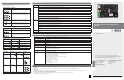
5 | LED descriptions
The B426 module includes the following on-board LEDs to assist
with troubleshooting issues.
Flash pattern Function
Flashes once
every 1 sec
Normal state: Indicates normal operation state.
3 quick fl ashes
every 1 sec
Communication error state: Indicates a bus
communication error. The module is not
receiving commands from the control panel.
On Steady Trouble state. Indicates a trouble condition
exists.
Off LED trouble state. Module is not powered, or
some other trouble condition prohibits the
module from controlling the heartbeat LED.
Table 5.1: Heartbeat LED descriptions
Flash pattern Function
RX (Receive)
fl ashes
Occurs when the module receives a message
over the network connection – UPD, TCP, or
DNS.
TX (Transmit)
fl ashes
Occurs when the module sends a message
over the network connection – UPD, TCP, or
DNS.
Table 5.2: RX and TX LEDs descriptions
LINK (yellow)
fl ash pattern
100mb (green)
fl ash pattern
Function
Off Off No Ethernet link
On Steady Off 10 BASE-T link
Flash Off 10 BASE-T activity
On Steady On Steady 100 BASE-T link
Flash On Steady 100 BASE-T activity
Table 5.3: Ethernet LINK and 100mb LEDs descriptions
6 | Certifi cations
Region Certifi cation
USA UL 365 – Police Station Connected Burglar Alarm Units and Systems
UL 609 – Local Burglar Alarm Units and Systems
UL 864 – Control Units and Accessories for Fire Alarm Systems (Including NFPA 72)
UL 985 – Household Fire Warning System Units
UL 1023 – Household Burglar Alarm System Units
UL 1076 – Proprietary Burglar Alarm Units and Systems
UL 1610 – Central Station Burglar Alarm Units
FCC Part 15 Class B, NIST FIPS-197 AES Certifi cation
(IP Communications)
Canada CAN/ULC S303 – Local Burglar Alarm Units and Systems
CAN/ULC S304 – Signal Receiving Centre and Premise Alarm Control Units
CAN/ULC S559 – Fire Signal Receiving Centres and Systems
ULC-ORD C1023 – Household Burglar Alarm System Units
ULC-ORD C1076 – Proprietary Burglar Alarm Units and
Systems
ICES-003 – Digital Apparatus
EU EN 50130-4, EN 61000-6-3, EN 60950
Australia C-Tick
Table 5.4: Trouble conditions indicated through LEDs
Condition Heartbeat Transmit
(TX)
Receive
(RX)
Network cable
disconnected
On Steady Off 1 quick fl ash,
repeating
Obtaining an IP
address
On Steady Off 2 quick fl ashes,
repeating
Low bus
voltage
On Steady Off 3 quick fl ashes,
repeating
Internal failure On Steady On Steady On Steady
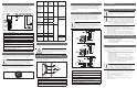
For complete installation, configuration, and testing instructions,
refer to the Conettix Ethernet Communication Module (B426) Installation
and Operation Guide provided on the supplied CD-ROM.
en Quick Start Guide
Conettix Ethernet Communication
Module
B426