
Specification Sheet
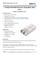


10Gtek Transceivers Co.,Ltd
Driving Your Next Generation Networks www.10gtek.com
E-mail:info@10gtek.com Tel: +86 755 2998 8100 Fax: +86 755 6162 4140
6
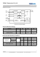
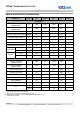
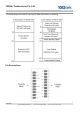
Pin
Signal Name
Description
Plug Seq.
Notes
1
V
EET
Transmitter Ground
1
2
TX FAULT
Transmitter Fault Indication
3
Note 1
3
TX DISABLE
Transmitter Disable
3
Note 2
4
SDA
SDA Serial Data Signal
3
5
SCL
SCL Serial Clock Signal
3
6
MOD_ABS
Module Absent. Grounded within the
module
3
7
RS0
Not Connected
3
8
LOS
Loss of Signal
3
Note 3
9
RS1
Not Connected
3
10
V
EER
Receiver ground
1
11
V
EER
Receiver ground
1
12
RD-
Inv. Received Data Out
3
Note 4
13
RD+
Received Data Out
3
Note 4
14
V
EER
Receiver ground
1
15
V
CCR
Receiver Power Supply
2
16
V
CCT
Transmitter Power Supply
2
17
V
EET
Transmitter Ground
1
18
TD+
Transmit Data In
3
Note 5
19
TD-
Inv. Transmit Data In
3
Note 5
20
V
EET
Transmitter Ground
1
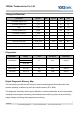
Notes:
Plug Seq.: Pin engagement sequence during hot plugging.
1) TX Fault is an open collector output, which should be pulled up with a 4.7k~10kΩ resistor on the host board to a voltage
between 2.0V and Vcc+0.3V. Logic 0 indicates normal operation; Logic 1 indicates a laser fault of some kind. In the low
state, the output will be pulled to less than 0.8V.
2) Laser output disabled on TDIS >2.0V or open, enabled on TDIS <0.8V.
3) LOS is open collector output. Should be pulled up with 4.7k~10kΩ on host board to a voltage between 2.0V and 3.6V.
Logic 0 indicates normal operation; logic 1 indicates loss of signal.
4) RD-/+: These are the differential receiver outputs. They are internally AC-coupled 100 differential lines which should be
terminated with 100Ω (differential) at the user SERDES.
5) TD-/+: These are the differential transmitter inputs. They are internally AC-coupled, differential lines with 100Ω differential
termination inside the module.